


 Welcome to Deves Technet.com Forums. I encourage everyone to register so we can get a better idea of the traffic and its usefulness. Please leave a word or two describing your stay and what we can do to make it more enjoyable. Thanks!
 Tweet
Tweet
Note: As with all of the content on this website, you can simply click on any picture to get its largest size. In this way, we can maintain the clearest definition to make it easier for you to see the detail. If the picture is so big you can't see all of it on your screen, all you have to do is hold down CONTROL and move the mouse wheel up and down to resize!
A truck just needs a trailer hitch. It's a truck! But not just any hitch, we want to do this right. What made this project challenging was the underbed spare tire carrier. The solution adds more stability to the tire carrier in that it eliminates the J-Hook that sways around under the truck during driving and gives it a very solid mount of its own. This is optional however. Before we start, let's decide on how we want it to look and behave when we are done.
Solution Criteria:
Materials List:
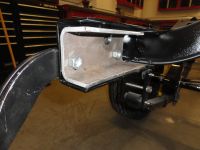
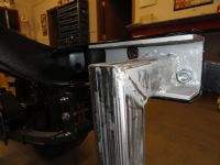
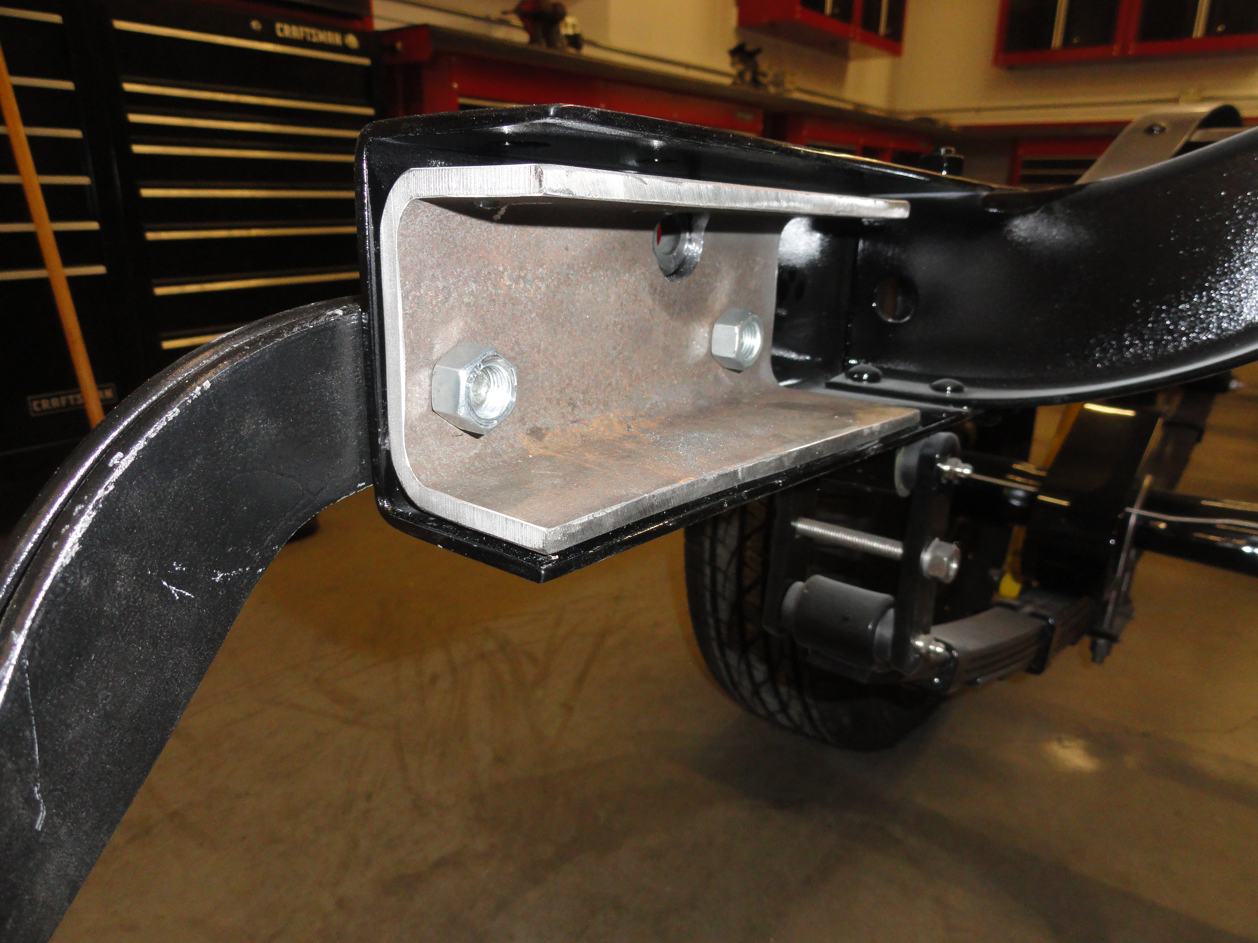
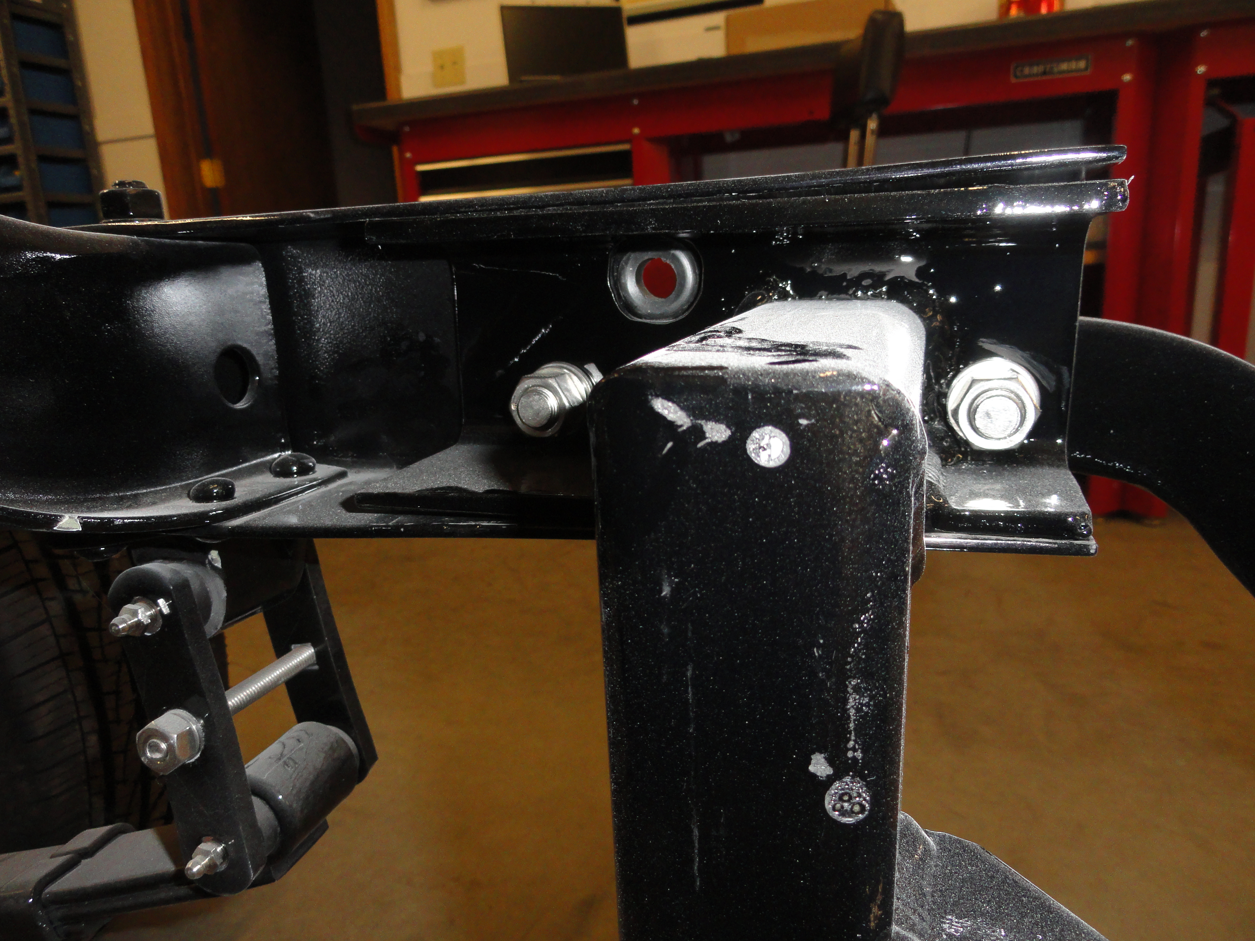
Start by making two 3 inch by 7 inch rails to go inside of your frame rail. Cut two pieces of 3" square tubing 7" long. Lay the square tubing inside the frame flush with the frame ending as shown upper left. With a Sharpie, mark the framerails contour on the tubing. The top is about 2 inches, but the bottom bevels out further. Without moving the piece, also mark the holes carefully and any other holes needed for wiring, etc. The 3 inch should be marked with the tubing resting on the bottom of the rail. With your favorite cutting tool, cut the 3 x 7 along the cut line. I use a Makita 4 inch grinder with thin cutting wheel. Do this on both sides since they are opposite each other. You will end up with the piece shown above.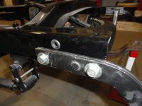 On the outside of where this piece goes, there is a rubber grommet for feeding wires through for the taillights. You will need to make that hole bigger than the outside hole because the grommet needs to seat inside the hole properly. I drilled mine out to 5/8". Also, drill the two 1/2" holes for attaching the bumper brackets. Be precise so you aren't elongating holes, then check the fit to make sure that piece bolts in nicely. You are on your way!
NOTE: We cut a lot of angles in this process, but they are ALL 45's.
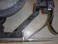
With your favorite saw for cutting thick metal tubing, I use a Makita 12" Dry Cut Saw, cut two of the 2" square tubing as follows: Overall length is 5-1/4", One end is straight cut, the other is cut at a 45 degree angle. Ending dimensions on the top, 5-1/4", on the bottom, 3-1/4". If I am not making myself clear, take a look at the picture to the right. We are cutting the piece protruding inwards towards the center of the frame. This piece isn't finished yet. We want to remove the bottom "floor" of that particular piece so it fits into the channel using the channels floor. This effectively drops the piece down 3/16". Put the piece where it's going to go, then mark the bottom of the piece with a sharpie. Cut out the bottom of the piece so that if fits perfectly into the channel. Do this on both sides.
NOTE: In some places I talk about using welding magnets to keep things square, other places I say to use a level. Use both with the level over-ruling the magnets. The success of the entire process will depend on how level things sit in relation to the frame and to the ground.
Now using the same picture to the right, cut the one going downwards. This one is 6-1/2" on the outside, 4-1/2" on the inside. Remember to cut two of them, just like before. Next we will cut the two that connect to this dropdown assembly. This one measures 12-3/4" on the inside and out, but it's NOT 12-3/4 overall. Both ends have 45 degree angles on this one. Both angles go the same way. Check out the picture on the left. Notice how it does not perfectly match up on the outside. Take your straight edge and mark that jog with a sharpie and cut it off. You can then take a piece of some of your cutoffs to cap it off. If both length measurements are 12-3/4" then you did it right.
Now for the tricky part. It's very important when welding these pieces together that they remain perfectly straight and true so that both sides come together properly. To accomplish this, we will weld one piece at a time, making sure to square things up as you go. The first piece that protrudes out from the frame, inside that 3 inch channel, rests on the bottom of that channel. Set that piece into your little channel piece so that it is 1-1/2" away from the front. Mark that, then put a nut and bolt together inside the hole to make sure you can still get a socket on the nut once it's welded. Allow for weld in that area. I really like my 90 degree welding magnets for this, but however you do it, weld it level and square. To prepare for welding, you will need to grind a rounded edge into the bottom so that it fits the contour of the 3 inch properly. Take your time.
Do both sides this way, being careful that both sides measure the same. Bolt the assembly to the frame. If you want it to slide in and out without a hammer, put a washer in each hole between the frame and the assembly (on one side only) to "shorten" the hitch for easier removal and installation. Floor Measurement: Make sure your truck is sitting on flat concrete. Since your leaf springs could be tensioned differently, do NOT assume your measurements will be the same on both sides. Measure from the top of the framerail to the floor. Record that number on both sides. If one side is less than the other, jack up your truck on one side until those numbers are the same. Once this first piece is welded, measure the end of that to the floor, making sure both sides are identical. Use a level to verify this piece is level with the ground as well as square to the inside. Once you have that welded properly, you are ready for the downward piece.
The downward piece should be just as level all the way around. Measure the bottom of each one after its tacked to make sure they both measure the same from the floor. I use a grinder to bevel the edges of the angles to be welded for deeper penetration. This IS a hitch we are taking about so good penetration is essential. On this project I even used multi-pass welding techniques for added strength. Prepare the 12-3/4" piece for welding. Remember a good level is your friend here. Once the downward piece is in place, we can move on to the angled one. Look at the pictures carefully to be sure you are welding it in the right way. Weld this piece as shown butting up the bottom of the downward piece flush with this one. Tack it in place, measure from the floor to the outward end, both sides carefully. It should be perfectly level across. This particular piece must be perfectly level so that it follows the bumper. We will not install the cross piece just yet.
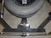
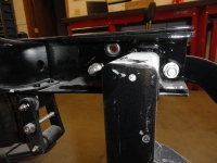
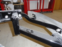
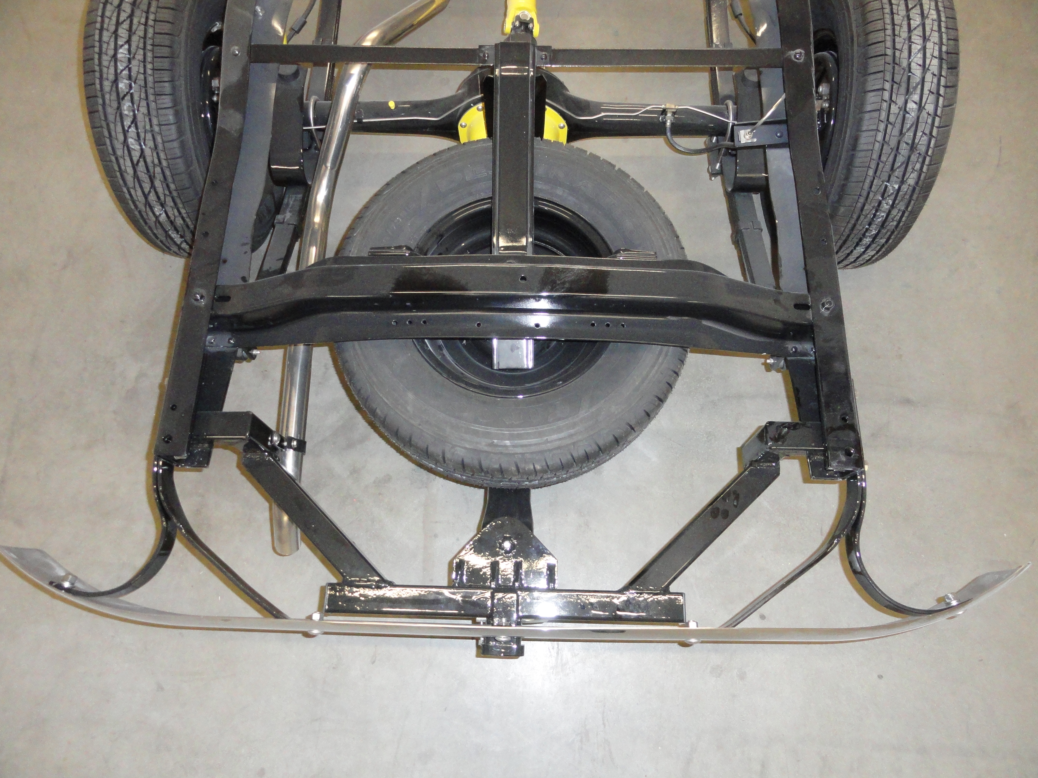
For our next feat of amazement, we will cut a piece of 2 inch square tubing 24-1/2 inches for our cross piece. This piece will sit about flush with the bottom of the bumper if you did everything above right. Don't panic if it's just a little low, but it should be VERY close to flush. There is alot to accomplish with this piece before we weld it in. Set this piece on a flat table and cut a piece of 1/4" plate steel that is 5" x 7-1/2". This will serve as our spare tire carrier mounting surface. As shown, round the edges so that the 5 inch dimension bevels down to 2 inches. Mark the center of this plate left to right (3-3/4") then mark it 3 inches in from the non-beveled side. This is for drilling a 1/2" hole for a bolt to secure the spare tire carrier. Drill the 1/2" hole then secure a bolt with a weld nut through it to hold the weld nut in place. Weld in the nut on the top side as shown.
Because this piece will have alot of stress on it due to its association with the spare tire carrier, cut 4 1-1/2" triangles for supporting this piece. With the entire assembly in the very center of the 24-1/2 cross piece, and both it and the 1/4"x 5" x 7-1/2" piece sitting flat on the table, butt them together and tack them as flat and straight as possible. Turn it over and finish the welds making sure not to warp, then install the triangles for further support. Grind the bottom weld so that everything is flush underneath.
Still looking at the picture left above, make a 1-1/2" x 4" strip out of your remaining 1/4" material. This piece will have a 90 degree bend at 2". then it will need to be contoured to match the profile of your bumper, then drilled in the appropriate place for the bumper bolt to go through. This isn't just decorative, this is part of the support system. The beauty of this hitch design is it uses the bumper, bumper brackets, and spare tire carrier to enhance its strength and rigidity. When you are finished it will all be a part of the hitch system. Find an anvil, or something to beat that contour into that strip in the right place, then set it aside for now. We do not yet know exactly where the hole will be or how far forward to place the strip, so save drilling and welding that for later.
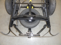
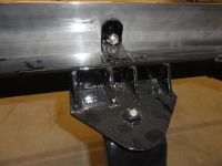
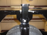
Cut a piece of 2-1/2" square tubing 5 inches long for the receiver. To beef up this piece to meet government standards, cut a 1 inch piece of 3" square tubing and weld it in place around the 2-1/2" piece as shown. Now go to Harbor Freight, Northern Tool, or your favorite trailer supply and get the receiver part with the ball on it. It will have a hole left to right for a large pin that will secure the hitch. Put it in place and measure for drilling the hole in your 2-1/2" for that. Be sure to get a receiver that is not too long that it protrudes into your spare tire carrier bolt territory. Once you have everything accounted for, holes drilled, etc, go ahead and weld the receiver to your cross piece in the very center as shown.
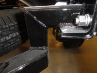
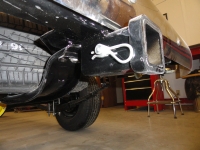
Now take the entire cross piece assembly over and fit it for welding. Clamp it into place where it is in the very center and matching everything. If everything has gone as planned, it will be almost flush with the bottom of the bumper and will not be touching anything its not supposed to. Put that 90 degree strip with the bumper contour in place and push it against the bumper. Clamp it in place tightly and mark the hole for drilling. Take the cross assembly off and weld that piece in, then drill the 1/2" hole. Remember you have to get a nut back there for the bumper bolt. It will be very close. If everything goes as planned, it will look like the picture above. Now, put your cross assembly back on and this time bolt the bumper to it. Tack weld the cross assembly in place being sure to bevel the welds, clean off the mill scale, and do multiple passes to ensure you have a hitch that will outlast the truck.
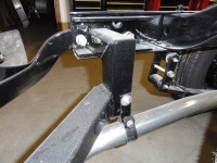
Now remove the entire hitch assembly as a whole and take out those washers you put in between the channel and the framerail, then reinstall everything. The last small order of business is relocating the exhaust pipe a little. The solution I came up with is shown on the left. I drilled a hole in the assembly and attached a new bracket. Lastly, once the hitch was painted with automotive epoxy primer and gloss black urethane paint, I put plastic caps in the ends. They look nicer and keep the moisture out. See how easy that was! Keep those emails coming!
More Pictures available at The Site Archive Page!
This article was first published at DevesTechNet.com (c)2015 All Rights Reserved
A truck just needs a trailer hitch. It's a truck! But not just any hitch, we want to do this right. What made this project challenging was the underbed spare tire carrier. The solution adds more stability to the tire carrier in that it eliminates the J-Hook that sways around under the truck during driving and gives it a very solid mount of its own. This is optional however. Before we start, let's decide on how we want it to look and behave when we are done.
Solution Criteria:
- We don't want to see the finished product, it should be hidden behind the bumper. With the exception of the Receiver of course.
- We want to honor and even augment the underbed spare tire carrier. If you like your J-Hook assembly, you can keep it.
- We want it to be the strongest possible hitch for a stock truck using the frame rails and the stock bumper system for ultimate support structure.
- We want to have the option to give the underbed spare tire carrier an anchor that is much stronger than the J-Hook system with no side to side movement.
- We want to make no compromises to any related stock system.
Materials List:
- 3 inch tubing with 3/16" walls - 30 inches
- 2-1/2" tubing with 3/16" walls - 6 inches
- 2 inch tubing with 3/16" walls - 49 inches
- 1/4" plate 5" x 7-1/2"
- 1/4" plate 1-1/2" x 10"
Start by making two 3 inch by 7 inch rails to go inside of your frame rail. Cut two pieces of 3" square tubing 7" long. Lay the square tubing inside the frame flush with the frame ending as shown upper left. With a Sharpie, mark the framerails contour on the tubing. The top is about 2 inches, but the bottom bevels out further. Without moving the piece, also mark the holes carefully and any other holes needed for wiring, etc. The 3 inch should be marked with the tubing resting on the bottom of the rail. With your favorite cutting tool, cut the 3 x 7 along the cut line. I use a Makita 4 inch grinder with thin cutting wheel. Do this on both sides since they are opposite each other. You will end up with the piece shown above.
 On the outside of where this piece goes, there is a rubber grommet for feeding wires through for the taillights. You will need to make that hole bigger than the outside hole because the grommet needs to seat inside the hole properly. I drilled mine out to 5/8". Also, drill the two 1/2" holes for attaching the bumper brackets. Be precise so you aren't elongating holes, then check the fit to make sure that piece bolts in nicely. You are on your way!
NOTE: We cut a lot of angles in this process, but they are ALL 45's.
With your favorite saw for cutting thick metal tubing, I use a Makita 12" Dry Cut Saw, cut two of the 2" square tubing as follows: Overall length is 5-1/4", One end is straight cut, the other is cut at a 45 degree angle. Ending dimensions on the top, 5-1/4", on the bottom, 3-1/4". If I am not making myself clear, take a look at the picture to the right. We are cutting the piece protruding inwards towards the center of the frame. This piece isn't finished yet. We want to remove the bottom "floor" of that particular piece so it fits into the channel using the channels floor. This effectively drops the piece down 3/16". Put the piece where it's going to go, then mark the bottom of the piece with a sharpie. Cut out the bottom of the piece so that if fits perfectly into the channel. Do this on both sides.
NOTE: In some places I talk about using welding magnets to keep things square, other places I say to use a level. Use both with the level over-ruling the magnets. The success of the entire process will depend on how level things sit in relation to the frame and to the ground.
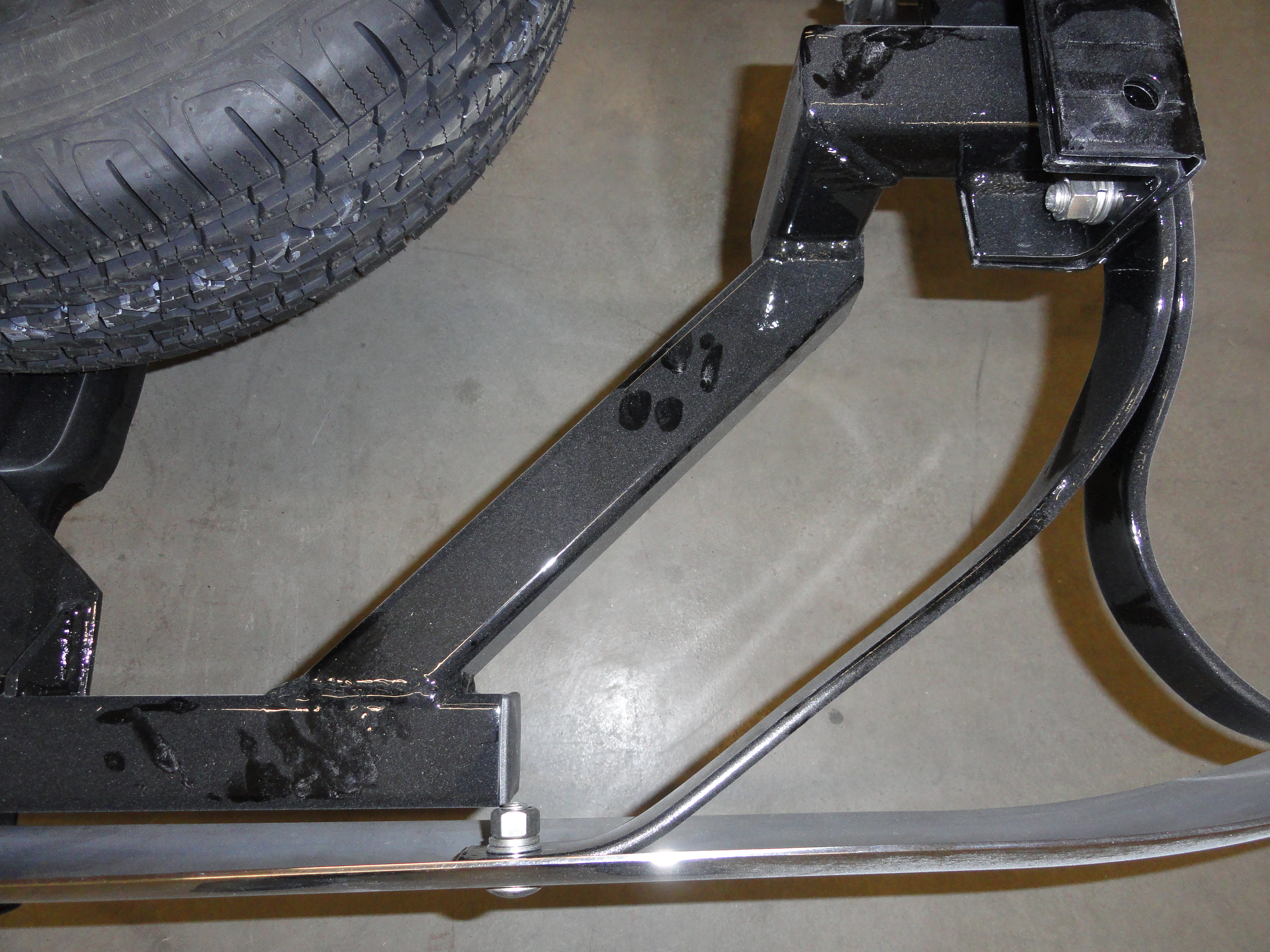
Now using the same picture to the right, cut the one going downwards. This one is 6-1/2" on the outside, 4-1/2" on the inside. Remember to cut two of them, just like before. Next we will cut the two that connect to this dropdown assembly. This one measures 12-3/4" on the inside and out, but it's NOT 12-3/4 overall. Both ends have 45 degree angles on this one. Both angles go the same way. Check out the picture on the left. Notice how it does not perfectly match up on the outside. Take your straight edge and mark that jog with a sharpie and cut it off. You can then take a piece of some of your cutoffs to cap it off. If both length measurements are 12-3/4" then you did it right.


Now for the tricky part. It's very important when welding these pieces together that they remain perfectly straight and true so that both sides come together properly. To accomplish this, we will weld one piece at a time, making sure to square things up as you go. The first piece that protrudes out from the frame, inside that 3 inch channel, rests on the bottom of that channel. Set that piece into your little channel piece so that it is 1-1/2" away from the front. Mark that, then put a nut and bolt together inside the hole to make sure you can still get a socket on the nut once it's welded. Allow for weld in that area. I really like my 90 degree welding magnets for this, but however you do it, weld it level and square. To prepare for welding, you will need to grind a rounded edge into the bottom so that it fits the contour of the 3 inch properly. Take your time.
Do both sides this way, being careful that both sides measure the same. Bolt the assembly to the frame. If you want it to slide in and out without a hammer, put a washer in each hole between the frame and the assembly (on one side only) to "shorten" the hitch for easier removal and installation. Floor Measurement: Make sure your truck is sitting on flat concrete. Since your leaf springs could be tensioned differently, do NOT assume your measurements will be the same on both sides. Measure from the top of the framerail to the floor. Record that number on both sides. If one side is less than the other, jack up your truck on one side until those numbers are the same. Once this first piece is welded, measure the end of that to the floor, making sure both sides are identical. Use a level to verify this piece is level with the ground as well as square to the inside. Once you have that welded properly, you are ready for the downward piece.
The downward piece should be just as level all the way around. Measure the bottom of each one after its tacked to make sure they both measure the same from the floor. I use a grinder to bevel the edges of the angles to be welded for deeper penetration. This IS a hitch we are taking about so good penetration is essential. On this project I even used multi-pass welding techniques for added strength. Prepare the 12-3/4" piece for welding. Remember a good level is your friend here. Once the downward piece is in place, we can move on to the angled one. Look at the pictures carefully to be sure you are welding it in the right way. Weld this piece as shown butting up the bottom of the downward piece flush with this one. Tack it in place, measure from the floor to the outward end, both sides carefully. It should be perfectly level across. This particular piece must be perfectly level so that it follows the bumper. We will not install the cross piece just yet.
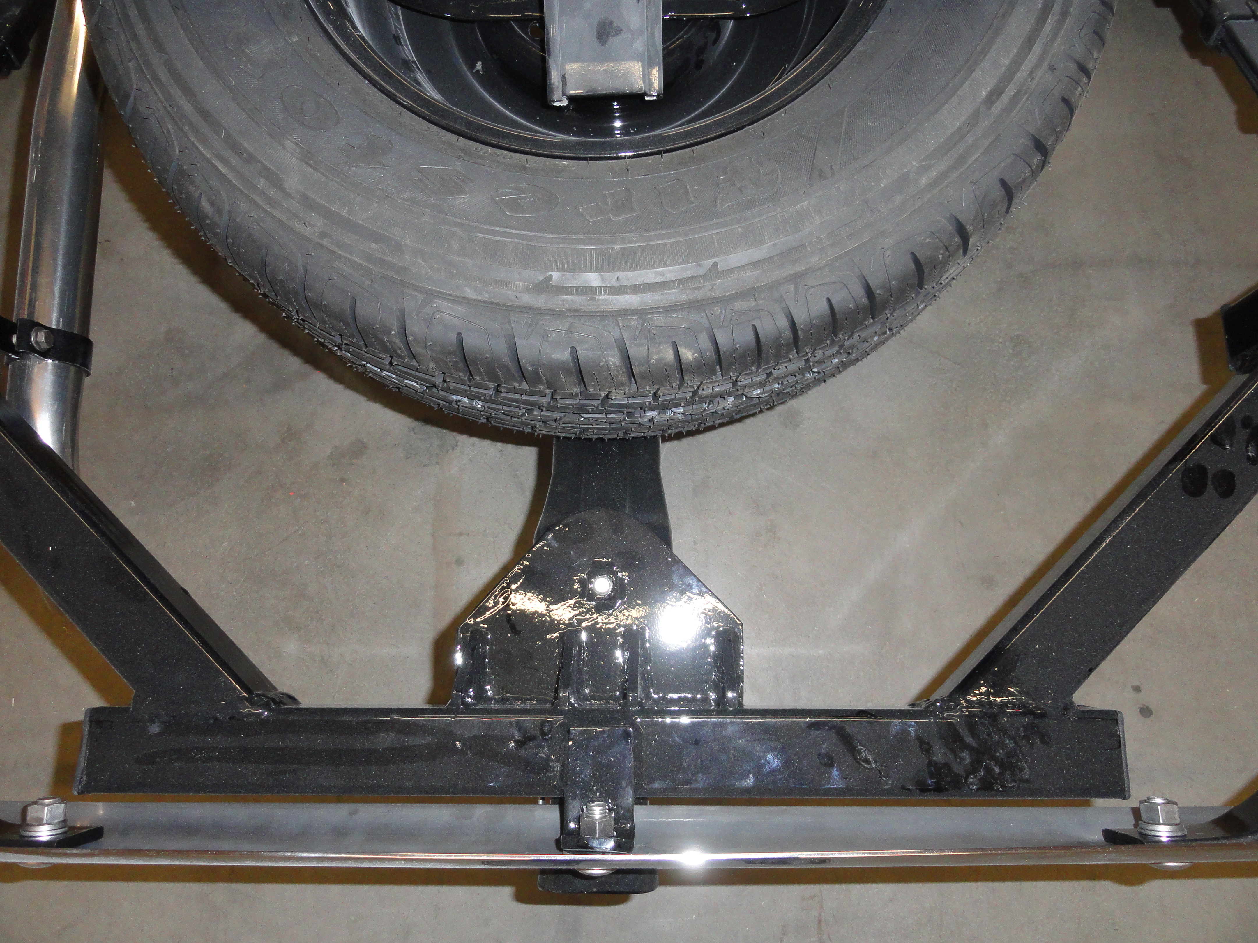
For our next feat of amazement, we will cut a piece of 2 inch square tubing 24-1/2 inches for our cross piece. This piece will sit about flush with the bottom of the bumper if you did everything above right. Don't panic if it's just a little low, but it should be VERY close to flush. There is alot to accomplish with this piece before we weld it in. Set this piece on a flat table and cut a piece of 1/4" plate steel that is 5" x 7-1/2". This will serve as our spare tire carrier mounting surface. As shown, round the edges so that the 5 inch dimension bevels down to 2 inches. Mark the center of this plate left to right (3-3/4") then mark it 3 inches in from the non-beveled side. This is for drilling a 1/2" hole for a bolt to secure the spare tire carrier. Drill the 1/2" hole then secure a bolt with a weld nut through it to hold the weld nut in place. Weld in the nut on the top side as shown.
Because this piece will have alot of stress on it due to its association with the spare tire carrier, cut 4 1-1/2" triangles for supporting this piece. With the entire assembly in the very center of the 24-1/2 cross piece, and both it and the 1/4"x 5" x 7-1/2" piece sitting flat on the table, butt them together and tack them as flat and straight as possible. Turn it over and finish the welds making sure not to warp, then install the triangles for further support. Grind the bottom weld so that everything is flush underneath.
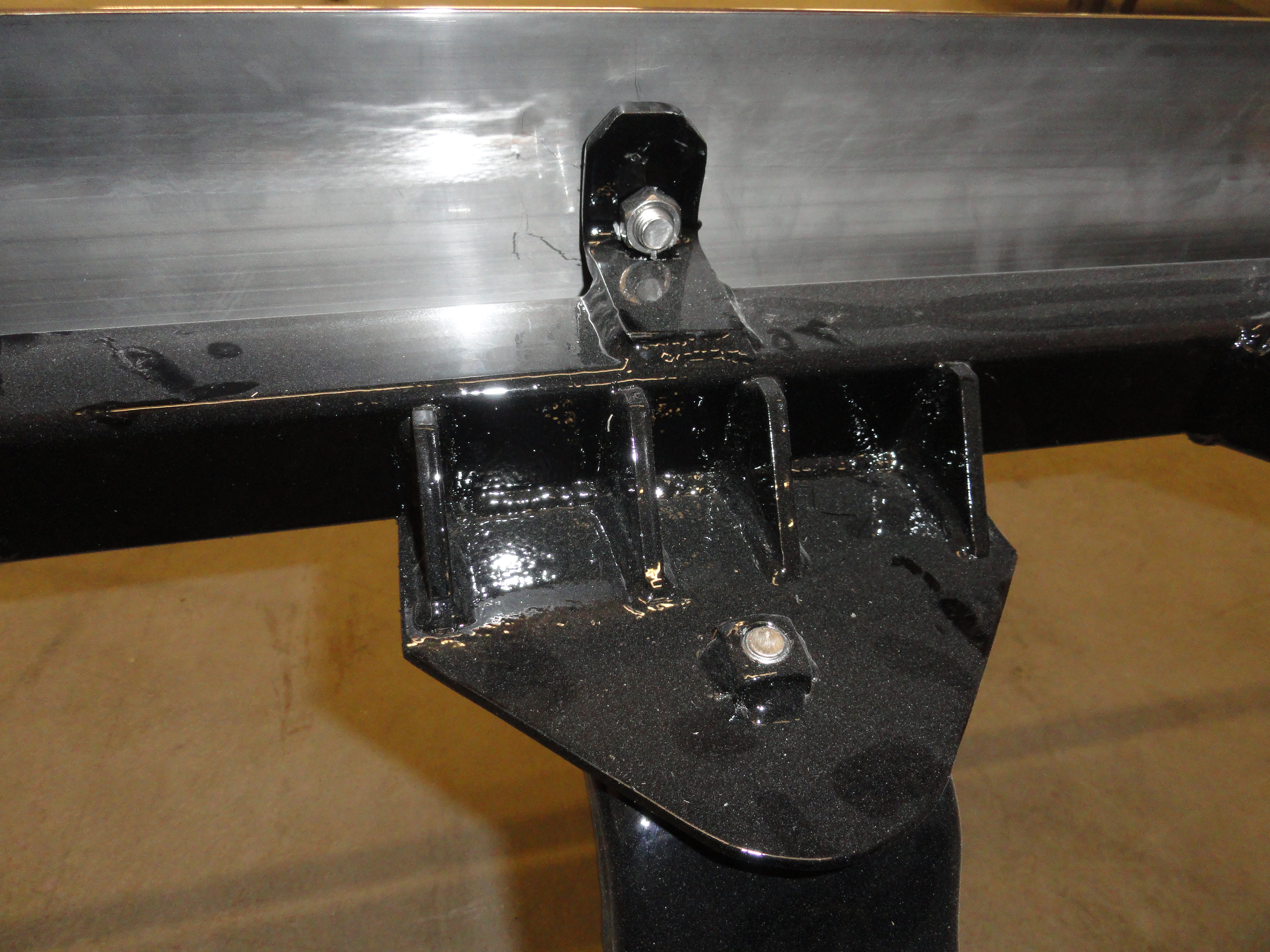
Still looking at the picture left above, make a 1-1/2" x 4" strip out of your remaining 1/4" material. This piece will have a 90 degree bend at 2". then it will need to be contoured to match the profile of your bumper, then drilled in the appropriate place for the bumper bolt to go through. This isn't just decorative, this is part of the support system. The beauty of this hitch design is it uses the bumper, bumper brackets, and spare tire carrier to enhance its strength and rigidity. When you are finished it will all be a part of the hitch system. Find an anvil, or something to beat that contour into that strip in the right place, then set it aside for now. We do not yet know exactly where the hole will be or how far forward to place the strip, so save drilling and welding that for later.

Cut a piece of 2-1/2" square tubing 5 inches long for the receiver. To beef up this piece to meet government standards, cut a 1 inch piece of 3" square tubing and weld it in place around the 2-1/2" piece as shown. Now go to Harbor Freight, Northern Tool, or your favorite trailer supply and get the receiver part with the ball on it. It will have a hole left to right for a large pin that will secure the hitch. Put it in place and measure for drilling the hole in your 2-1/2" for that. Be sure to get a receiver that is not too long that it protrudes into your spare tire carrier bolt territory. Once you have everything accounted for, holes drilled, etc, go ahead and weld the receiver to your cross piece in the very center as shown.
Now take the entire cross piece assembly over and fit it for welding. Clamp it into place where it is in the very center and matching everything. If everything has gone as planned, it will be almost flush with the bottom of the bumper and will not be touching anything its not supposed to. Put that 90 degree strip with the bumper contour in place and push it against the bumper. Clamp it in place tightly and mark the hole for drilling. Take the cross assembly off and weld that piece in, then drill the 1/2" hole. Remember you have to get a nut back there for the bumper bolt. It will be very close. If everything goes as planned, it will look like the picture above. Now, put your cross assembly back on and this time bolt the bumper to it. Tack weld the cross assembly in place being sure to bevel the welds, clean off the mill scale, and do multiple passes to ensure you have a hitch that will outlast the truck.


Now remove the entire hitch assembly as a whole and take out those washers you put in between the channel and the framerail, then reinstall everything. The last small order of business is relocating the exhaust pipe a little. The solution I came up with is shown on the left. I drilled a hole in the assembly and attached a new bracket. Lastly, once the hitch was painted with automotive epoxy primer and gloss black urethane paint, I put plastic caps in the ends. They look nicer and keep the moisture out. See how easy that was! Keep those emails coming!
More Pictures available at The Site Archive Page!
This article was first published at DevesTechNet.com (c)2015 All Rights Reserved