


 Welcome to Deves Technet.com Forums. I encourage everyone to register so we can get a better idea of the traffic and its usefulness. Please leave a word or two describing your stay and what we can do to make it more enjoyable. Thanks!
 Tweet
Tweet
Here at the shop I am always trying to look into how things work. I was working on a low fuel warning and decided to use what is already there in the Fuel Sender. Problem is, what IS already there (from an electro-mechanical perspective)? So I went through a few boxes and found a few Sending Units. Let's take a closer look.
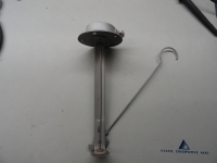
The Sending Unit to the left is a typical unit found in the 1947-1955 Chevy Trucks with the gas tank in the cab. The designers were smart in that they did not want raw voltage to be present at the tank so they use Ohm values to 'Send' to the Gauge. The Gauge is then merely a calibrated analog Ohm Meter. The residual signal is too low to cause a spark, so it made for the perfect system. Reading the Sender with an Ohmmeter, a full tank is 30 ohms and an empty tank is something less than one ohm. A float is attached to the hook on the end and the ohm value is translated to what you see on your fuel gauge. Nowadays they do this electronically and a mechanical contraption is no longer present in your modern gas tank, however, it was ingenious for its time.
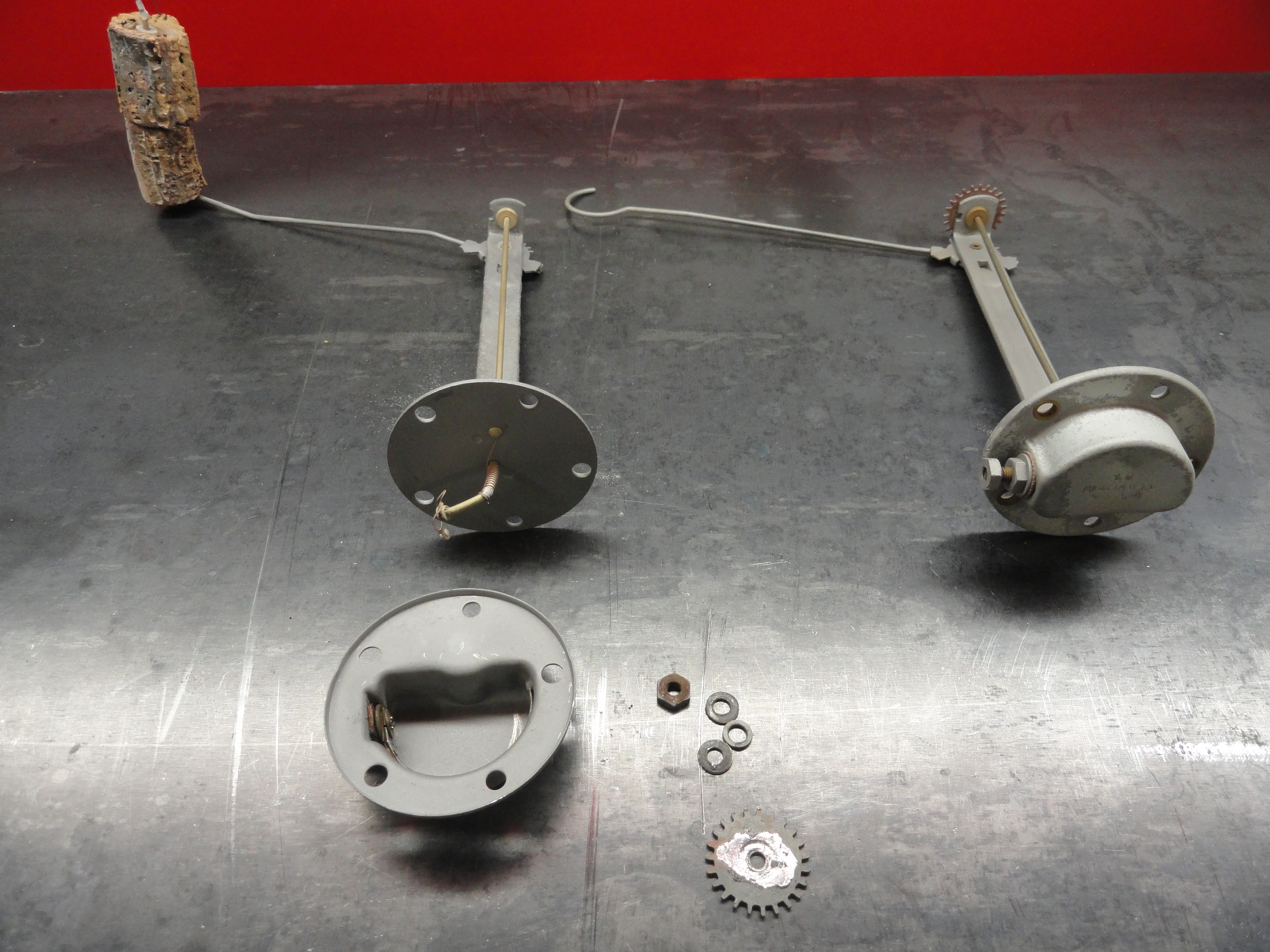
The larger trucks Sending Unit looks the same, but has a 50 ohm Sender. Let's take one apart and see what's in there! Here is one out of a 1950 1-1/2 Ton Truck with the tank outside on the frame rail. It was TOAST! From the outside, you would swear there is no making it work ever again. Everything rusted together, old fuel varnish just caked on everything. Anyone would think it's time for a new sender. A little blasting and some PB Blaster, and we have a salvageable unit. If I am lucky in re-assembly, I can put this back into service.

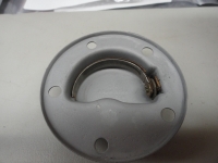
It is not necessary to take the gear off the bottom, but I was curious as to what holds it in place. It is pressed in, then it is soldered to the brass bushing. Not a lot to it. The inside, once cleaned up looks like the picture on the right. The resistor strip is placed in so that the highest ohm value is on the left and the lowest is on the right. A plastic insulator is present behind this resistive strip to enable it to work properly, then the screw is insulated from the housing with a plastic insert. Of course these exact pieces would not be available to replace them, but once you understand the idea of how they are insulated from the cover, a thin piece of rubber works just fine.

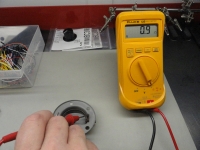
This is the highest reading I can get from this unit. This would represent a full tank of gas. The right side picture is the lowest reading I can get from this unit representing an empty tank. The way to clean this properly is to remove the strip (very carefully) and take the assembly out together with the screw so as not to break any connections, then blast the cover nicely, replace the insulator behind and very gingerly put it all back together ensuring you have no contact with the cover except on the left where there is supposed to be. Once its clean and back together, a little electronic contact spray to clean the resistive strip with a soft brush will get it back in service. A very small rubber grommet would work at the hole. I was able to salvage the original pieces enough to reuse everything.
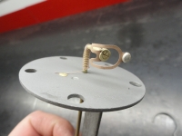

Left is a picture of the mechanical wiper that moves along the resistor to give the proper reading. Notice the spring. This 'spring resistance' gives the gauge a more steady reading. I had to drill the rivets out that hold the cover together, and their WAS a gasket there. I will make another gasket and use gasket sealer to hold the two pieces together. This will have no affect on operation since the 5 screws that hold it to the tank will provide continuity. This type of system is very finicky on getting the proper grounding. I also took the time to bend the wiper outwards just a bit to ensure it rubbed solidly on the resistor strip. The gear is more soldered on to the brass bushing than it is pressed on, so I do not expect for this to be a problem.
So the moral of the story is, that is how a vintage fuel sender works. I did not do this to save a sending unit, more just to see what's inside and to get an idea of how to configure my low fuel warning circuit. I will make it adjustable so that it can be set anywhere from 0-30 ohms so the end user can adjust when they want to see a low fuel warning. Seeya next week!
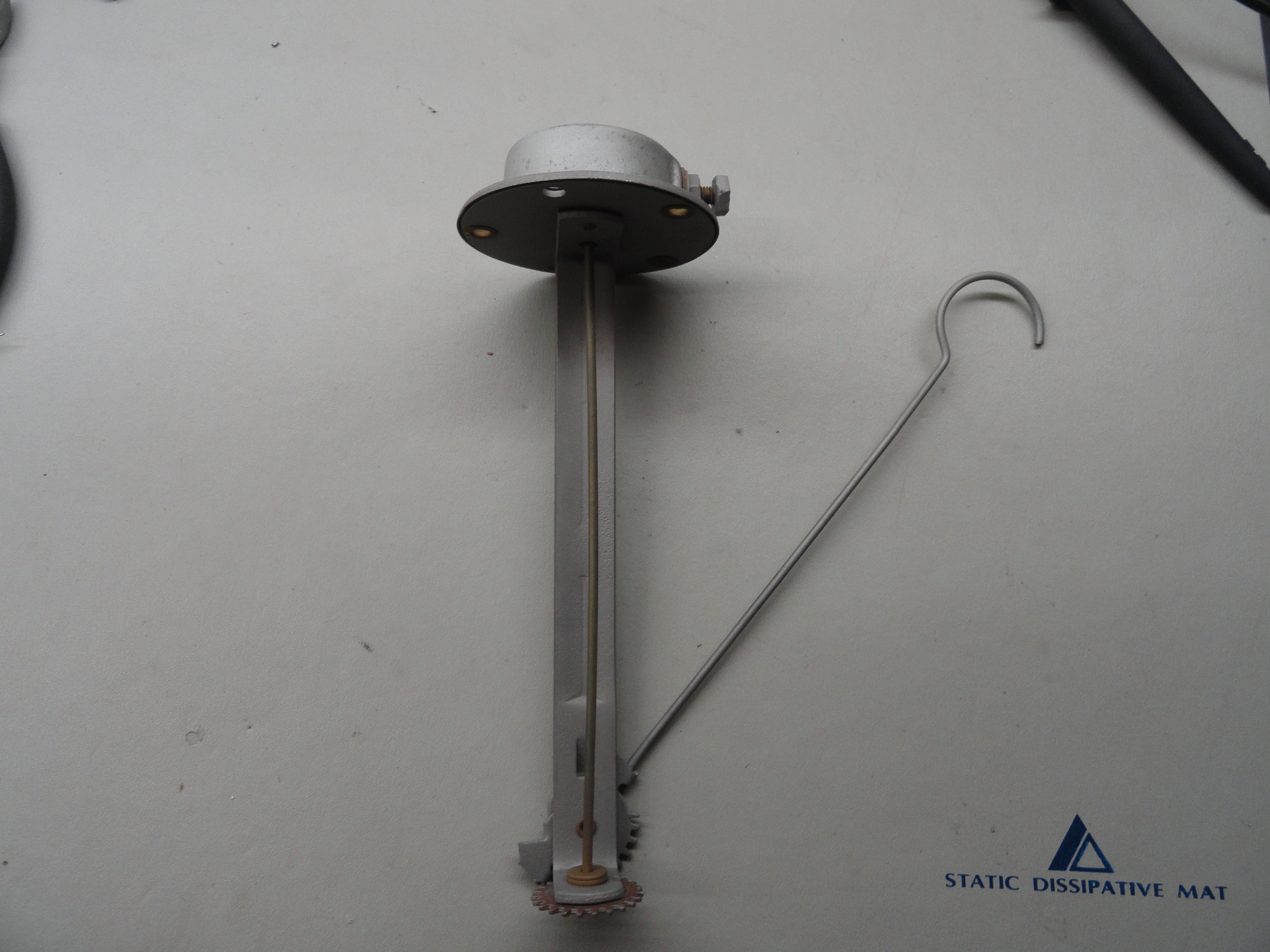
The Sending Unit to the left is a typical unit found in the 1947-1955 Chevy Trucks with the gas tank in the cab. The designers were smart in that they did not want raw voltage to be present at the tank so they use Ohm values to 'Send' to the Gauge. The Gauge is then merely a calibrated analog Ohm Meter. The residual signal is too low to cause a spark, so it made for the perfect system. Reading the Sender with an Ohmmeter, a full tank is 30 ohms and an empty tank is something less than one ohm. A float is attached to the hook on the end and the ohm value is translated to what you see on your fuel gauge. Nowadays they do this electronically and a mechanical contraption is no longer present in your modern gas tank, however, it was ingenious for its time.
The larger trucks Sending Unit looks the same, but has a 50 ohm Sender. Let's take one apart and see what's in there! Here is one out of a 1950 1-1/2 Ton Truck with the tank outside on the frame rail. It was TOAST! From the outside, you would swear there is no making it work ever again. Everything rusted together, old fuel varnish just caked on everything. Anyone would think it's time for a new sender. A little blasting and some PB Blaster, and we have a salvageable unit. If I am lucky in re-assembly, I can put this back into service.
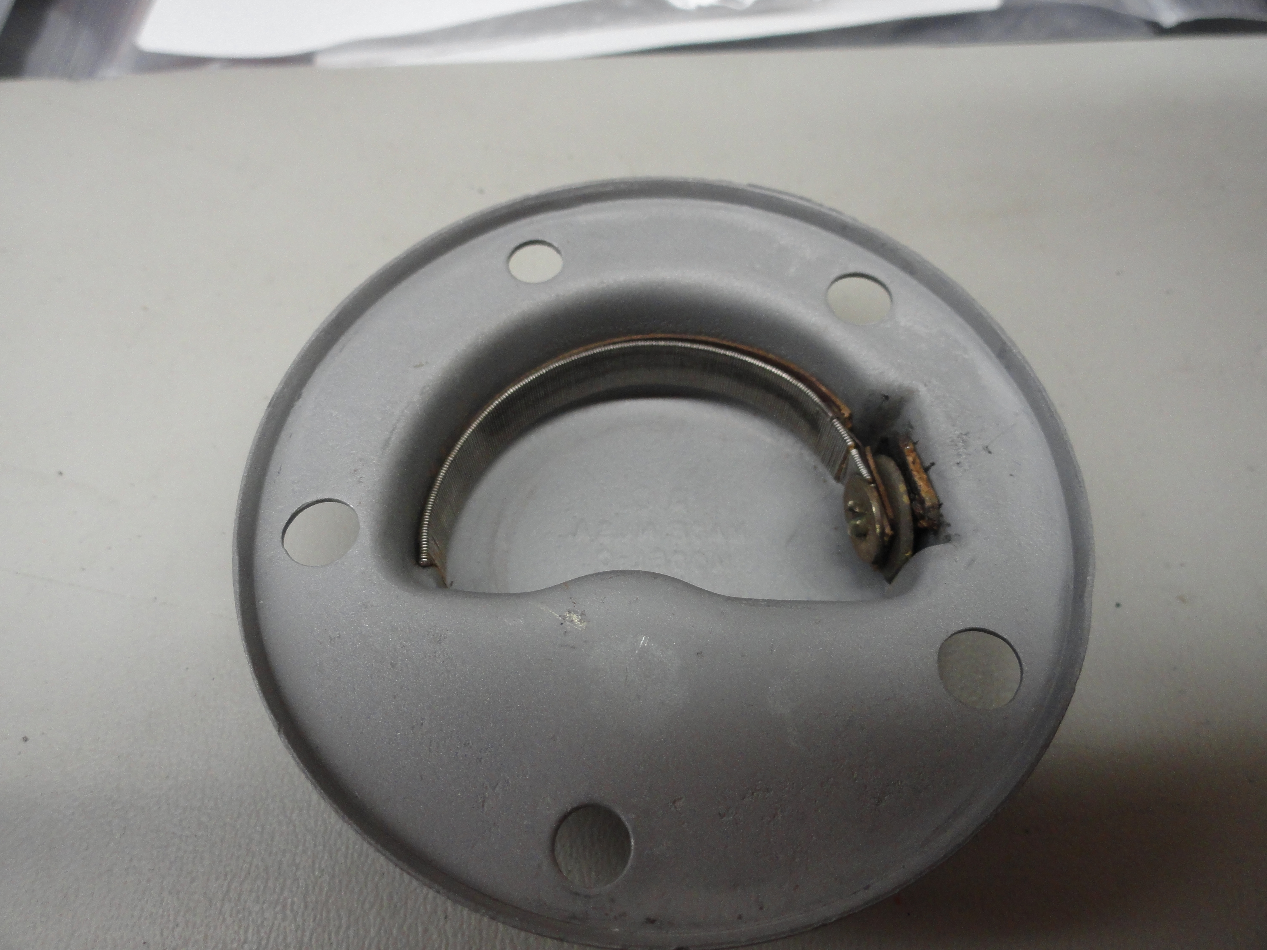
It is not necessary to take the gear off the bottom, but I was curious as to what holds it in place. It is pressed in, then it is soldered to the brass bushing. Not a lot to it. The inside, once cleaned up looks like the picture on the right. The resistor strip is placed in so that the highest ohm value is on the left and the lowest is on the right. A plastic insulator is present behind this resistive strip to enable it to work properly, then the screw is insulated from the housing with a plastic insert. Of course these exact pieces would not be available to replace them, but once you understand the idea of how they are insulated from the cover, a thin piece of rubber works just fine.
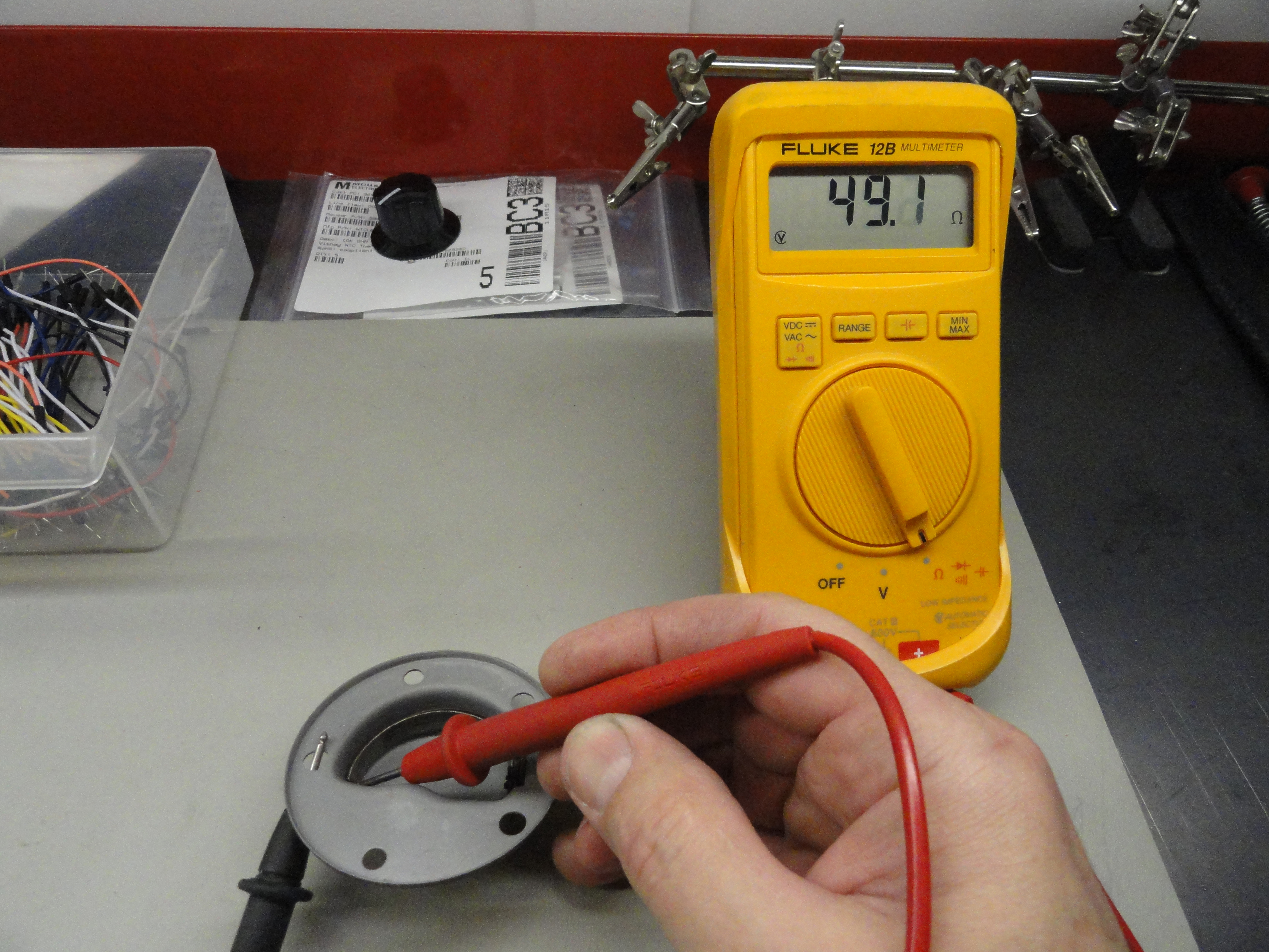
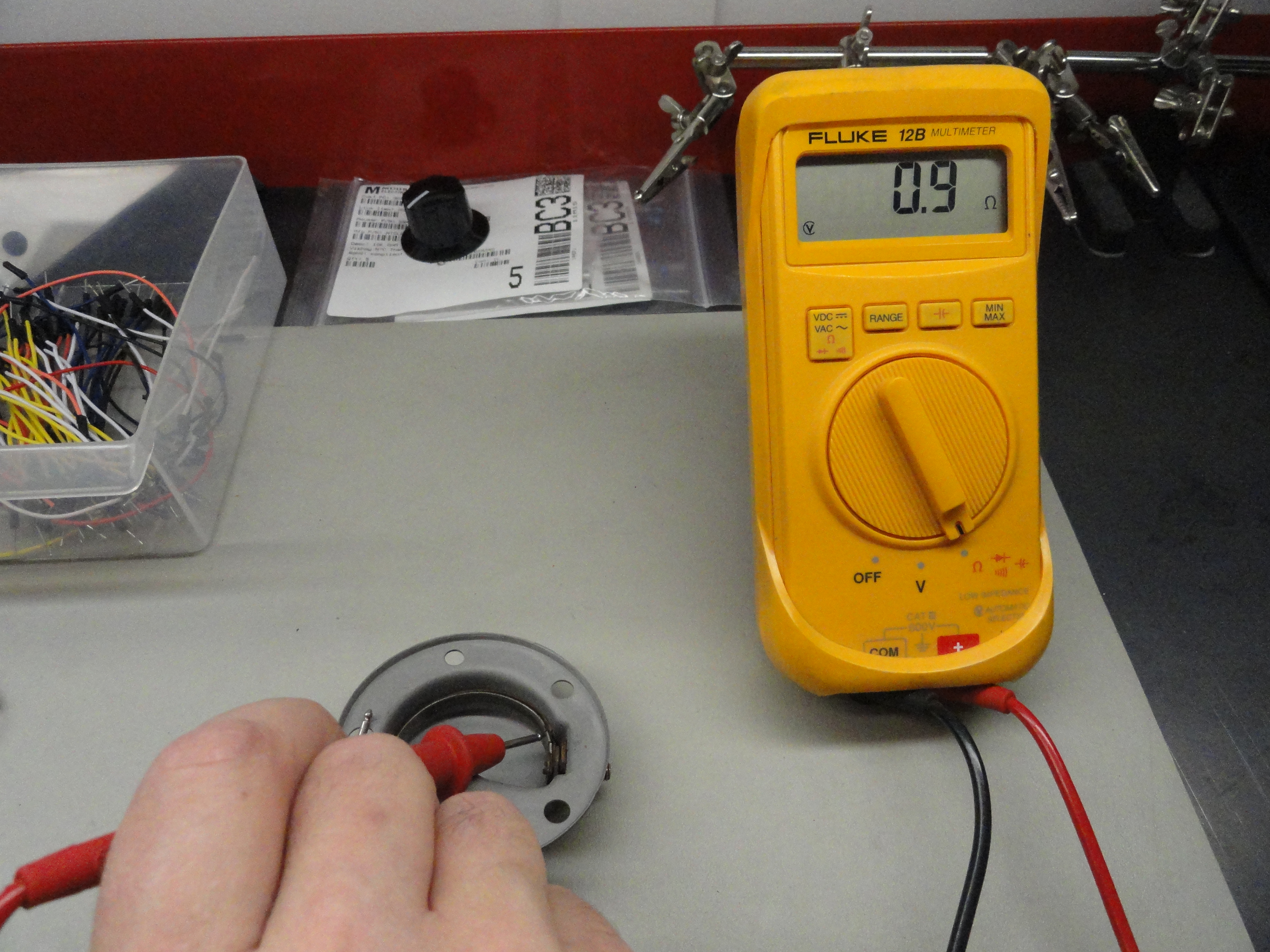
This is the highest reading I can get from this unit. This would represent a full tank of gas. The right side picture is the lowest reading I can get from this unit representing an empty tank. The way to clean this properly is to remove the strip (very carefully) and take the assembly out together with the screw so as not to break any connections, then blast the cover nicely, replace the insulator behind and very gingerly put it all back together ensuring you have no contact with the cover except on the left where there is supposed to be. Once its clean and back together, a little electronic contact spray to clean the resistive strip with a soft brush will get it back in service. A very small rubber grommet would work at the hole. I was able to salvage the original pieces enough to reuse everything.

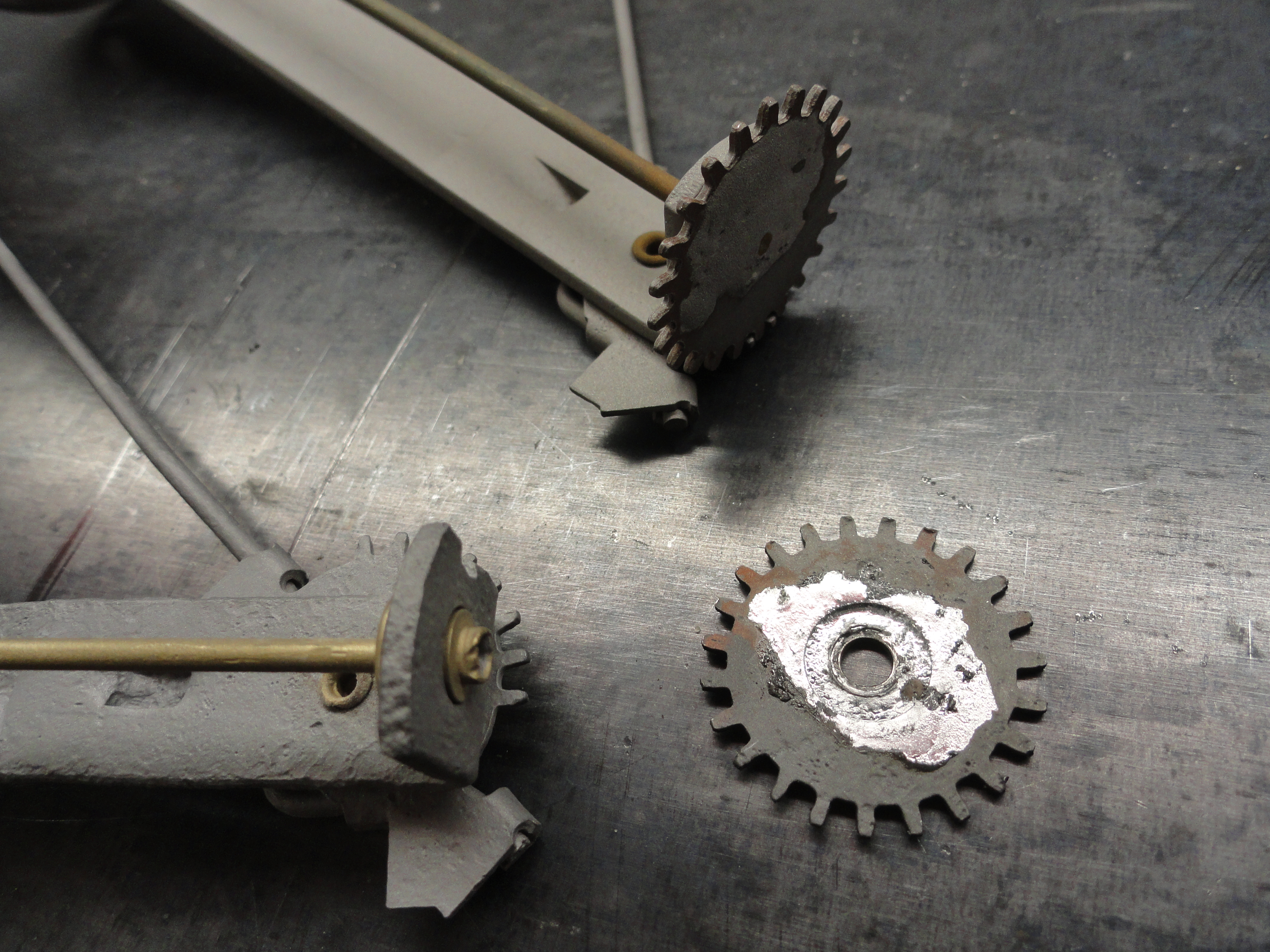
Left is a picture of the mechanical wiper that moves along the resistor to give the proper reading. Notice the spring. This 'spring resistance' gives the gauge a more steady reading. I had to drill the rivets out that hold the cover together, and their WAS a gasket there. I will make another gasket and use gasket sealer to hold the two pieces together. This will have no affect on operation since the 5 screws that hold it to the tank will provide continuity. This type of system is very finicky on getting the proper grounding. I also took the time to bend the wiper outwards just a bit to ensure it rubbed solidly on the resistor strip. The gear is more soldered on to the brass bushing than it is pressed on, so I do not expect for this to be a problem.
So the moral of the story is, that is how a vintage fuel sender works. I did not do this to save a sending unit, more just to see what's inside and to get an idea of how to configure my low fuel warning circuit. I will make it adjustable so that it can be set anywhere from 0-30 ohms so the end user can adjust when they want to see a low fuel warning. Seeya next week!