Replacing the Wiring Harness in a 1953 3100 (Part 2):
Preliminary Step Six:
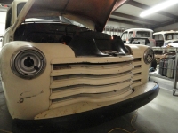
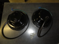 This week we should be able to finish up on the Preliminary steps for ensuring this 1953 3100's electrical system is ready for a new Harness. On the outside of the truck we have Headlight Buckets to prep for the new harness, Park Light fixtures, Tail Light fixtures and I will throw in the Dome Light for good measure. The headlight buckets can be in really sad shape if you have never had them out, so since we have to change the headlights anyway, let's see what they look like. The condition of the metal was okay, but we have to get a new rubber grommet into the back of the bucket for the new harness, so let's take it apart. While I am at it, I will blast everything and repaint the pieces since rust has taken over so badly. The bucket comes out with 9 #8 sheet metal screws. The inside bucket assembly comes out by pulling the spring upwards and out, then once apart, remove the two threaded adjustment inserts and special screws that go with them. The vendor of your choice sells headlight grommets so be sure to have two of them ready for the job. The old ones are solidly brittle and will not protect the new wiring.
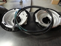 Once you have the buckets ready to install, the two Headlight Harnesses are ready. It is very important that all connections and all wiring are perfect for the headlights because the stock configuration does not use a relay system. The Headlights themselves are now 6020 12 volt Halogen Sealed Beams. They replace the old 6014's. Also, while you are in this area, you will notice on your inner fenders a grommet where the headlight harness feeds from the bucket through the inner fender out to the terminal block. Replace that grommet if needed. With new terminal blocks, refurbished buckets and new grommets, the headlight harness will go in easily.
Preliminary Step Seven:
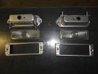 The front Park Lights are next. Remove the bezel with the two stainless recessed screws then carefully remove the lens. It's glass so be careful not to drop it. Once that is done, get underneath the grill with a 7/16 wrench to remove the two nuts holding the fixture in place. Lots to do here. The reason is because we want to incorporate turn signals. We do not want to hang extra lights on the truck to do it, so we will install the vendor of your choice dual filament fixture kit. I do not have pictures of the modification, but once you get the kit, it's really a no brainer. You have to make the grommet hole 3/4" round and drill a second mounting screw hole. Its pretty much as simple as that. New screws are in the kit and now you have provision for dual filament bulbs. This is only necessary for the front park lights. The rears are already equipped with two bulbs. This will require a new turn signal switch for this rig because the old Flash-All 999 only has 4 wires. We need something akin to the SignalStat 900. This one has 7 wire support. This is so we do not have to change any wiring, the harness already has this capability configured. I think I paid about $50 for a new SignalStat 900 and another $15 for the special flasher.
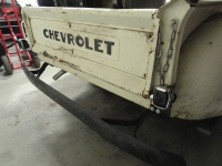
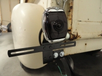
The truck we are dealing with is in very poor condition and had about 3 different trailer lights of different varieties bolted willy nilly on the back of the truck. I went with the vendor of your choice new taillights. They make the left one with a license plate lense on the bottom so they are different. They also have the nice brackets for a stock mounting. The interesting thing about these tail lights is the two bulbs are the same, just one is placed lower than the other. If you want the brake lights to be the most dominant, connect the black wire to the stoplight switch.
Preliminary Step Eight:
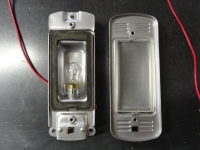
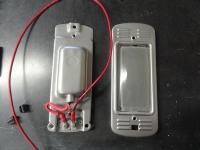 Okay, the outside is ready for the new harness, let's get the dome light squared away. I was lucky because the headliner is missing. (if you consider that lucky). I cannot imagine doing this with the headliner installed because later you will be stringing a wire up the A-Pillar to the dome light. Once again we take everything apart. Use the electrical cleaner to clean the switch and check the entire light for serviceability. With an ohm meter, check to see if the switch is working nicely after cleaning. It's a simple one wire setup so ground is your negative lead and the bulb side of the switch is your positive lead. Check for continuity as you turn the switch on/off. Once that is good to go, you need to make sure there is a lead wire on the bulb that is long enough and of safe enough quality to use. You will be connecting the harness wire to your lead wire. I had to completely redo my wire to the bulb so I made mine 12 inches.
Preliminary Step Nine:
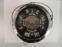 Now that we have the lighting systems square, let's take a look at the dash. (I would rather not and say we did, but that wouldn't be productive). The gauges both come out with four 7/16" nuts that are a pain to get to. Let's address that. You can kill your back or do it the easier way. The nuts are not that hard to feel for and remove by just sitting on the seat and doing it blind. Once you have the gauges loose, remove the oil pressure copper tube by removing the nut on the back of the gauge. This is a good time to replace the copper tube with a vendor of your choice copper tube kit. The next more difficult job is removing the water temperature line. NOT at the gauge! This line is a copper line filled with a special gas, so if you break that line, you are done and will have to order a new gauge. This means removing the line at the engine Head (drivers side near the firewall). Of course, drain the water system sufficiently to lower the water level or you will have water all over the place. Once the sensor is removed from the head, push it through the grommet/hole it came out of. Easier said than done since that grommet shares space with the throttle, choke and oil pressure lines. Once you have the sensor through the hole, you can remove all of the wires from the fuel gauge and ammeter and the gauge is free. Now you can get a vendor of your choice rebuild kit if you choose. New Chrome bezels, new decals, etc go a long way in making your truck look fantastic.
At this point, if the gauge system is stock and you are going to 12 volts, you will want to put a new 6 volt to 12 volt reducer at the fuel gauge or to do it right, order a new 12v native fuel gauge. In this case, I am not putting extra money into this project so I am using a 6.8 volt Zener Diode for the reduction. Install it with the stripe facing away from the gauge then put a barrel connector on the end that accepts the fuel gauge wire, and a round terminal on the fuel gauge end. Cover it with shrink tubing and you are done. Clean the terminals with a fine wire brush while it's out. The speedometer is just a matter of reaching under and removing the cable and the three light fixtures. Do not put the speedometer back in first! We need all the accessibility we can get to put in the harness.
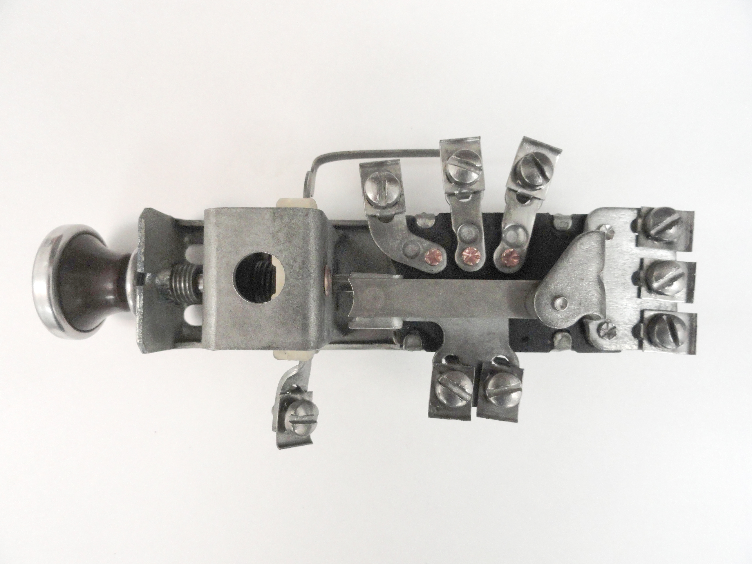
With the gauges out, you can now see the headlight switch. It is oriented so that you can easily see and disconnect all the wires. On the back where you cannot see is a spring loaded button. First pull the head light knob out fully, then push that spring loaded button and pull the knob out. With the knob out, you can use a large screwdriver to unscrew the special nut that holds the switch in. Remove all the wires, you do not care about where they go. The headlight switch is a key component in the stock harness configuration. We want to make sure it works perfectly. Clean this switch thoroughly and use your electrical contact cleaner liberally. Using a fine wire brush, clean the terminals. I used a Dremel with a wire brush attachment. Once it is clean, put it back in just the way you found it. The knob will push in and lock into place.
Preliminary Step 10:
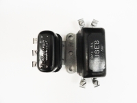
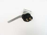
Remove the Dimmer Switch, Brake Light Switch, Horn Relay and Stop/Tail Fuse Block for the same reason. Inspection and Cleaning. The old Dimmer Switch might not be worth keeping, but clean it with contact spray and then put a meter on it. If it switches reliably after cleaning, it may be good to go. Electrical Contact Spray works wonders. The Horn Relay can be tested on the bench by placing the 12v battery to the center terminal, ground to the mounting area of the relay. Then with a jumper wire, clip one end of the jumper to the bottom terminal and just touch the mounting surface. If you hear a click your relay is probably working. I take it a step further and remove the cover and spray the contacts with contact cleaner. Install each of the aforementioned items exactly as you found them leaving the gauges out and setting on the floor of the truck. This will make connections easy.
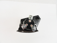
The Ignition Switch comes out with two 1/4" bolts/nuts from the bottom of the dash. You want to keep it together with its housing. Once again, check for serviceability and cleanliness, spray it good with contact cleaner to remove the dirt and crud built up in the keyway and set it aside for now. Do not reinstall the ignition switch just yet.
With all of the preliminaries out of the way, we can install this harness without any surprises. Next week we will start the harness install. Since nothing is left to chance, and all of our ancillary systems are addressed properly, this harness will go in perfectly. Seeya Next Week!
Preliminary Step Six:

 This week we should be able to finish up on the Preliminary steps for ensuring this 1953 3100's electrical system is ready for a new Harness. On the outside of the truck we have Headlight Buckets to prep for the new harness, Park Light fixtures, Tail Light fixtures and I will throw in the Dome Light for good measure. The headlight buckets can be in really sad shape if you have never had them out, so since we have to change the headlights anyway, let's see what they look like. The condition of the metal was okay, but we have to get a new rubber grommet into the back of the bucket for the new harness, so let's take it apart. While I am at it, I will blast everything and repaint the pieces since rust has taken over so badly. The bucket comes out with 9 #8 sheet metal screws. The inside bucket assembly comes out by pulling the spring upwards and out, then once apart, remove the two threaded adjustment inserts and special screws that go with them. The vendor of your choice sells headlight grommets so be sure to have two of them ready for the job. The old ones are solidly brittle and will not protect the new wiring.
 Once you have the buckets ready to install, the two Headlight Harnesses are ready. It is very important that all connections and all wiring are perfect for the headlights because the stock configuration does not use a relay system. The Headlights themselves are now 6020 12 volt Halogen Sealed Beams. They replace the old 6014's. Also, while you are in this area, you will notice on your inner fenders a grommet where the headlight harness feeds from the bucket through the inner fender out to the terminal block. Replace that grommet if needed. With new terminal blocks, refurbished buckets and new grommets, the headlight harness will go in easily.
Preliminary Step Seven:
 The front Park Lights are next. Remove the bezel with the two stainless recessed screws then carefully remove the lens. It's glass so be careful not to drop it. Once that is done, get underneath the grill with a 7/16 wrench to remove the two nuts holding the fixture in place. Lots to do here. The reason is because we want to incorporate turn signals. We do not want to hang extra lights on the truck to do it, so we will install the vendor of your choice dual filament fixture kit. I do not have pictures of the modification, but once you get the kit, it's really a no brainer. You have to make the grommet hole 3/4" round and drill a second mounting screw hole. Its pretty much as simple as that. New screws are in the kit and now you have provision for dual filament bulbs. This is only necessary for the front park lights. The rears are already equipped with two bulbs. This will require a new turn signal switch for this rig because the old Flash-All 999 only has 4 wires. We need something akin to the SignalStat 900. This one has 7 wire support. This is so we do not have to change any wiring, the harness already has this capability configured. I think I paid about $50 for a new SignalStat 900 and another $15 for the special flasher.

The truck we are dealing with is in very poor condition and had about 3 different trailer lights of different varieties bolted willy nilly on the back of the truck. I went with the vendor of your choice new taillights. They make the left one with a license plate lense on the bottom so they are different. They also have the nice brackets for a stock mounting. The interesting thing about these tail lights is the two bulbs are the same, just one is placed lower than the other. If you want the brake lights to be the most dominant, connect the black wire to the stoplight switch.
Preliminary Step Eight:

 Okay, the outside is ready for the new harness, let's get the dome light squared away. I was lucky because the headliner is missing. (if you consider that lucky). I cannot imagine doing this with the headliner installed because later you will be stringing a wire up the A-Pillar to the dome light. Once again we take everything apart. Use the electrical cleaner to clean the switch and check the entire light for serviceability. With an ohm meter, check to see if the switch is working nicely after cleaning. It's a simple one wire setup so ground is your negative lead and the bulb side of the switch is your positive lead. Check for continuity as you turn the switch on/off. Once that is good to go, you need to make sure there is a lead wire on the bulb that is long enough and of safe enough quality to use. You will be connecting the harness wire to your lead wire. I had to completely redo my wire to the bulb so I made mine 12 inches.
Preliminary Step Nine:
 Now that we have the lighting systems square, let's take a look at the dash. (I would rather not and say we did, but that wouldn't be productive). The gauges both come out with four 7/16" nuts that are a pain to get to. Let's address that. You can kill your back or do it the easier way. The nuts are not that hard to feel for and remove by just sitting on the seat and doing it blind. Once you have the gauges loose, remove the oil pressure copper tube by removing the nut on the back of the gauge. This is a good time to replace the copper tube with a vendor of your choice copper tube kit. The next more difficult job is removing the water temperature line. NOT at the gauge! This line is a copper line filled with a special gas, so if you break that line, you are done and will have to order a new gauge. This means removing the line at the engine Head (drivers side near the firewall). Of course, drain the water system sufficiently to lower the water level or you will have water all over the place. Once the sensor is removed from the head, push it through the grommet/hole it came out of. Easier said than done since that grommet shares space with the throttle, choke and oil pressure lines. Once you have the sensor through the hole, you can remove all of the wires from the fuel gauge and ammeter and the gauge is free. Now you can get a vendor of your choice rebuild kit if you choose. New Chrome bezels, new decals, etc go a long way in making your truck look fantastic.
At this point, if the gauge system is stock and you are going to 12 volts, you will want to put a new 6 volt to 12 volt reducer at the fuel gauge or to do it right, order a new 12v native fuel gauge. In this case, I am not putting extra money into this project so I am using a 6.8 volt Zener Diode for the reduction. Install it with the stripe facing away from the gauge then put a barrel connector on the end that accepts the fuel gauge wire, and a round terminal on the fuel gauge end. Cover it with shrink tubing and you are done. Clean the terminals with a fine wire brush while it's out. The speedometer is just a matter of reaching under and removing the cable and the three light fixtures. Do not put the speedometer back in first! We need all the accessibility we can get to put in the harness.

With the gauges out, you can now see the headlight switch. It is oriented so that you can easily see and disconnect all the wires. On the back where you cannot see is a spring loaded button. First pull the head light knob out fully, then push that spring loaded button and pull the knob out. With the knob out, you can use a large screwdriver to unscrew the special nut that holds the switch in. Remove all the wires, you do not care about where they go. The headlight switch is a key component in the stock harness configuration. We want to make sure it works perfectly. Clean this switch thoroughly and use your electrical contact cleaner liberally. Using a fine wire brush, clean the terminals. I used a Dremel with a wire brush attachment. Once it is clean, put it back in just the way you found it. The knob will push in and lock into place.
Preliminary Step 10:


Remove the Dimmer Switch, Brake Light Switch, Horn Relay and Stop/Tail Fuse Block for the same reason. Inspection and Cleaning. The old Dimmer Switch might not be worth keeping, but clean it with contact spray and then put a meter on it. If it switches reliably after cleaning, it may be good to go. Electrical Contact Spray works wonders. The Horn Relay can be tested on the bench by placing the 12v battery to the center terminal, ground to the mounting area of the relay. Then with a jumper wire, clip one end of the jumper to the bottom terminal and just touch the mounting surface. If you hear a click your relay is probably working. I take it a step further and remove the cover and spray the contacts with contact cleaner. Install each of the aforementioned items exactly as you found them leaving the gauges out and setting on the floor of the truck. This will make connections easy.

The Ignition Switch comes out with two 1/4" bolts/nuts from the bottom of the dash. You want to keep it together with its housing. Once again, check for serviceability and cleanliness, spray it good with contact cleaner to remove the dirt and crud built up in the keyway and set it aside for now. Do not reinstall the ignition switch just yet.
With all of the preliminaries out of the way, we can install this harness without any surprises. Next week we will start the harness install. Since nothing is left to chance, and all of our ancillary systems are addressed properly, this harness will go in perfectly. Seeya Next Week!


 Welcome to Deves Technet.com Forums. I encourage everyone to register so we can get a better idea of the traffic and its usefulness. Please leave a word or two describing your stay and what we can do to make it more enjoyable. Thanks!