


 Welcome to Deves Technet.com Forums. I encourage everyone to register so we can get a better idea of the traffic and its usefulness. Please leave a word or two describing your stay and what we can do to make it more enjoyable. Thanks!
 Tweet
Tweet
Replacing the Wiring Harness in a 1953 3100 (Part 3):
Welcome to Part 3 of Installing a Wiring Harness in a 1953 3100. We have covered almost all of the electrical components and systems that affect our new Harness Install. Of course, the Heater is not covered because it's only one wire going to your choice of switched or unswitched power. Let's talk about how a stock harness achieves switched or unswitched power. In modern vehicles we are used to a fuse/terminal block. This is how they discern the difference. Some parts of the terminal/fuse block are switched and others are unswitched. This is not the case with a stock 1953 truck harness. The way the stock systems accomplishes this capability is:
1) Headlight Switch - at the back of this switch is three terminals. This is where you attach your UNswitched power. This is for systems such as turn signals with hazard lights. Any system you want to work even when the Ignition switch is turned off. All three of those terminals are tied together so it is okay to stack systems on top of each other.
2) Ignition Switch - The top terminal (as installed) is where you stack your switched items. Things that you want to only be active when the ignition switch is turned ON. A Tachometer, the Heater System, things like this come to mind.
While this is not ideal in today's world with all of the accessories available, it was just fine in 1953 and I would argue it works just fine today as well. You just have to be strategic about it. With the SignalStat 900 Turn Signal Switch and the 263 Flasher Installed, we are now ready to install the harness. With each electrical item on the truck checked out thoroughly, this will go very smoothly. NO REALLY!!
Step One: The Harness
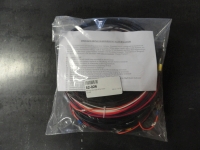
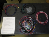 The new Harness comes in a plastic bag with two sheets of paper. These two sheets are your instructions. Surprisingly, there was no wiring diagram! After getting over the shock of this being the case, as an old wire chaser in the Air Force, this was off putting, I decided it isn't necessary after all. Everything you need is included with a few minor exceptions. Included is the Main Harness, Two Headlight Harnesses, One Starter/Coil Harness, A Single Dome Light Wire, a bundle of extra wiring that is unmarked and some extra male terminals for stop light switch, horn switch and dome light.
Step Two: The Starter/Ignition Harness
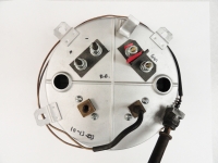 This two wire harness is something we can start with to get our feet wet. This has an 8 gauge wire and a 14 gauge wire. The thick wire goes to the starter and is placed on top of the main terminal on the starter where the positive from the battery connects. This is essentially your conduit for positive for the entire electrical system. This harness goes through the Starter/Ignition Grommet on the firewall. Put the wires through the grommet first. A common problem people run into right away is which terminal on the Ammeter do you connect the battery/starter to? Many times, people connect it wrong which means the Ammeter will read backwards. Let's not do that. Attach this 8 gauge wire to Ammeter Negative. Ammeter Negative is the Discharge terminal on the Ammeter. I over think these things and it almost drove me crazy trying to decide which terminal to use. Now you do not have to worry about it.
The ignition wire goes from the ballast resistor on the firewall (if you are using a points system) to the Ignition Switch top terminal. This concludes this small harness and now we can move on to bigger things.
Step Three: The Headlight Harnesses
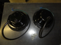
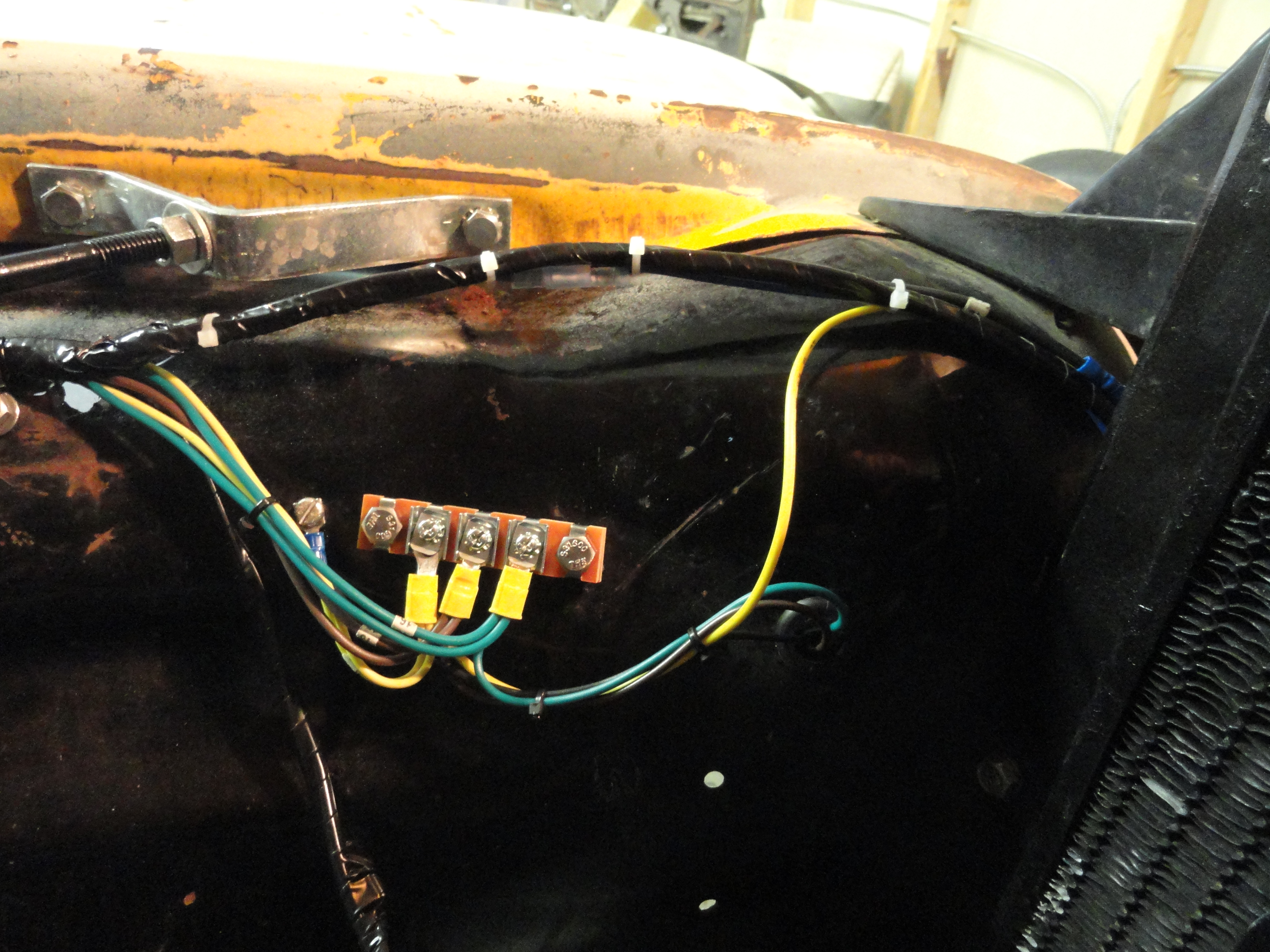
Once you have your Bucket Grommets installed, you can thread these two harnesses (one through each bucket) into the bucket from the front, with the terminals coming out the back. Now, reach through the headlight hole and push the terminal ends through the inner fender grommet hole. Replace that grommet if you haven't already. Once the wires are near the terminal blocks on the inner fender, you can install the headlight buckets and headlights. 9 sheet metal screws, two adjustment screws, a spring and a bezel later, you can now wire the headlight wires to the terminals. The three terminals are as follows:
1) Front most terminal screw nearest the headlight - High Beam
2) Center terminal screw - Low Beam
3) Rear most terminal screw nearest the firewall - Parking Lights
You will be stacking the main harness wires on top of these screws so don't tighten yet.
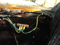
Step Four: The Dome Light
The reason we put this here is because we want to get rid of all of the contents of the Harness package before we go to the main harness. You will find a single wire labeled with the appropriate number for the dome light in the package. It's one wire but it's not the easiest one. This wire simply goes from the headlight switch, straight up the A-pillar right beside it and up to the dome light. Locate the old dome light wire and using electrical tape, butt them together so the profile is very thin and tape them up carefully without creating a large blob. Once they are secure, pull the old wire from the roof side and thread the new wire into the old wires position. This is easier said than done. I had some sharp obstruction that broke the line so I went to Plan B and fished it with safety wire, then did the same thing. That worked. Connect the dome light to the new wire and use those wire clips that you see clipped to that lip on the roof side. The clips I am referring to are pictured in the archive. Connect the other end to your headlight switch per the diagram on the back of page one of the instructions.
Step Five: The Main Harness:
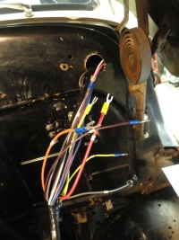
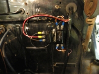 Sadly, or not, you are not going to see a lot of pictures of the install of the main harness. This is because it goes so fast, you are almost done before you get started. Spread the harness out and notice it has three main branches. One branch has gauge lights on it so that obviously goes through the main harness grommet hole. Cut your Main Grommet with an Exacto Knife so there is a slit from the center hole to the outside. Another branch will go down the firewall and get all of the electricals there, and another branch goes to the headlights. With it laid out across the fender in the proper orientation, go ahead and thread the gauge lights and all of that through the main harness grommet hole. Notice a set of terminals that look perfect for connection to the fuse block and horn relay. The wires are spaced perfectly for connection there. That is where you stop feeding through the hole. Go ahead and make the connections at the fuse block and horn relay. Rely heavily on the instructions. Each terminal has a number on it and the instructions tell you exactly where each wire goes. With the fuse block and horn relay wired, let's look at the headlight and park lamp branch.
Use those rubber Adel clamps to help secure the wires. I like to have a clamp every 3 feet or wherever the bundle gets a little stubborn. With the instructions close by, make the terminal connections at the inner fender. Do not overtighten these terminal screws! They strip out real easy! Snug is fine. Now with the harness connected for the headlights, the park lights will also require connection. I find that removing the hood latch plate assembly gets you perfect access to easily make these connections.
 Each park light has dual filaments now so you want the most dominant filament for the turn signals. You may have to experiment later and swap the wires around to get them correct to each other, so leave that area exposed for now. You need one of the filaments to go to the rear-most terminal on the inner fender. They did not supply a short wire for this so go to the bundle of extra wires they supplied and use one of those, or get some yellow wire to keep the color coding the same. There is a very convenient hole at the inner fender/radiator support to thread the horn wires and the park lamps through. The Main Harness has those connections so look over the instructions and it will be obvious as to what wire connects to what. With the park lights and horn wired, and everything secured nicely, we can move on to the lower firewall branch.
NOTE: I am not circumventing the manufacturer's instructions in this article. It is imperative that you look over those two sheets of paper and use them at each step. If I say something contrary to what they did, use THEIR instruction.
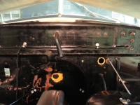
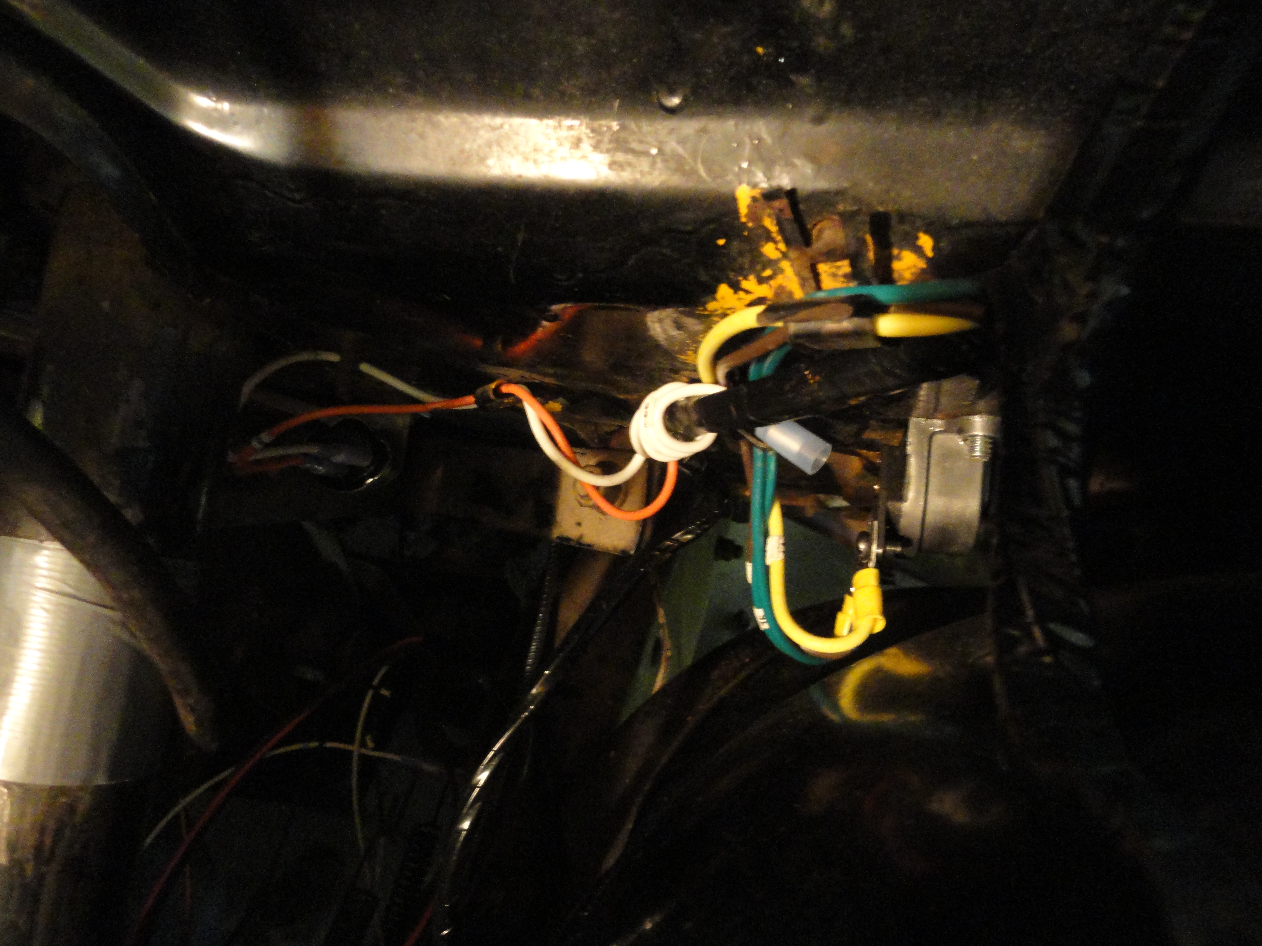
 The Lower Firewall Branch is for the Headlight Dimmer Switch, Brake Light Switch, Fuel Sending Unit, and Stop/Tail Light system. Thread this harness through the existing wiring clips down to the ground. Wire the Dimmer Switch and Brake Light Switch first. Once you have them secured and in their correct wire clips, thread the rest of the bundle down and into the driver's side frame rail. Be sure to route the bundle carefully taking into account moving levers and parts. Use Adel Clamps along the frame rail as much as possible to keep the wires secured.
Next week we will finish this 4 part series and check everything out. I am hopeful you are getting something out of this article and if there are any mistakes, be sure to let me know! Seeya Next Week!
Welcome to Part 3 of Installing a Wiring Harness in a 1953 3100. We have covered almost all of the electrical components and systems that affect our new Harness Install. Of course, the Heater is not covered because it's only one wire going to your choice of switched or unswitched power. Let's talk about how a stock harness achieves switched or unswitched power. In modern vehicles we are used to a fuse/terminal block. This is how they discern the difference. Some parts of the terminal/fuse block are switched and others are unswitched. This is not the case with a stock 1953 truck harness. The way the stock systems accomplishes this capability is:
1) Headlight Switch - at the back of this switch is three terminals. This is where you attach your UNswitched power. This is for systems such as turn signals with hazard lights. Any system you want to work even when the Ignition switch is turned off. All three of those terminals are tied together so it is okay to stack systems on top of each other.
2) Ignition Switch - The top terminal (as installed) is where you stack your switched items. Things that you want to only be active when the ignition switch is turned ON. A Tachometer, the Heater System, things like this come to mind.
While this is not ideal in today's world with all of the accessories available, it was just fine in 1953 and I would argue it works just fine today as well. You just have to be strategic about it. With the SignalStat 900 Turn Signal Switch and the 263 Flasher Installed, we are now ready to install the harness. With each electrical item on the truck checked out thoroughly, this will go very smoothly. NO REALLY!!
Step One: The Harness

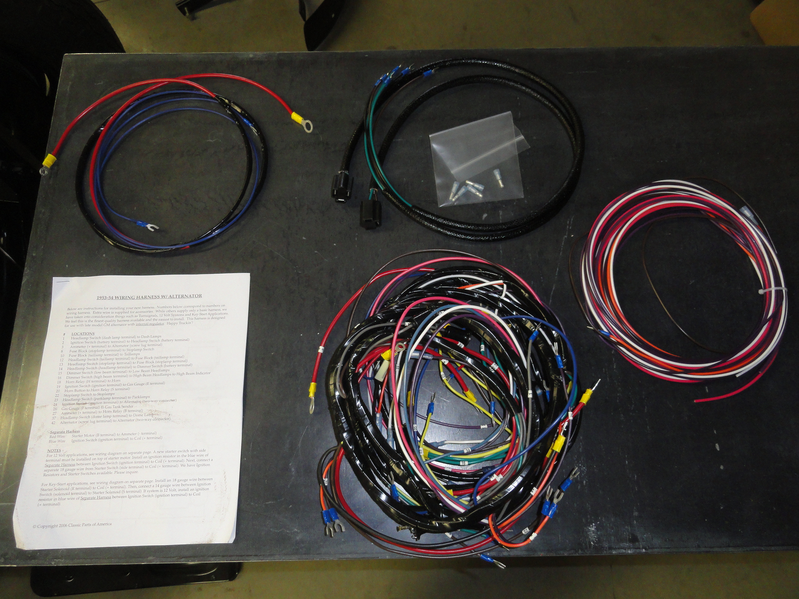 The new Harness comes in a plastic bag with two sheets of paper. These two sheets are your instructions. Surprisingly, there was no wiring diagram! After getting over the shock of this being the case, as an old wire chaser in the Air Force, this was off putting, I decided it isn't necessary after all. Everything you need is included with a few minor exceptions. Included is the Main Harness, Two Headlight Harnesses, One Starter/Coil Harness, A Single Dome Light Wire, a bundle of extra wiring that is unmarked and some extra male terminals for stop light switch, horn switch and dome light.
Step Two: The Starter/Ignition Harness

 This two wire harness is something we can start with to get our feet wet. This has an 8 gauge wire and a 14 gauge wire. The thick wire goes to the starter and is placed on top of the main terminal on the starter where the positive from the battery connects. This is essentially your conduit for positive for the entire electrical system. This harness goes through the Starter/Ignition Grommet on the firewall. Put the wires through the grommet first. A common problem people run into right away is which terminal on the Ammeter do you connect the battery/starter to? Many times, people connect it wrong which means the Ammeter will read backwards. Let's not do that. Attach this 8 gauge wire to Ammeter Negative. Ammeter Negative is the Discharge terminal on the Ammeter. I over think these things and it almost drove me crazy trying to decide which terminal to use. Now you do not have to worry about it.
The ignition wire goes from the ballast resistor on the firewall (if you are using a points system) to the Ignition Switch top terminal. This concludes this small harness and now we can move on to bigger things.
Step Three: The Headlight Harnesses
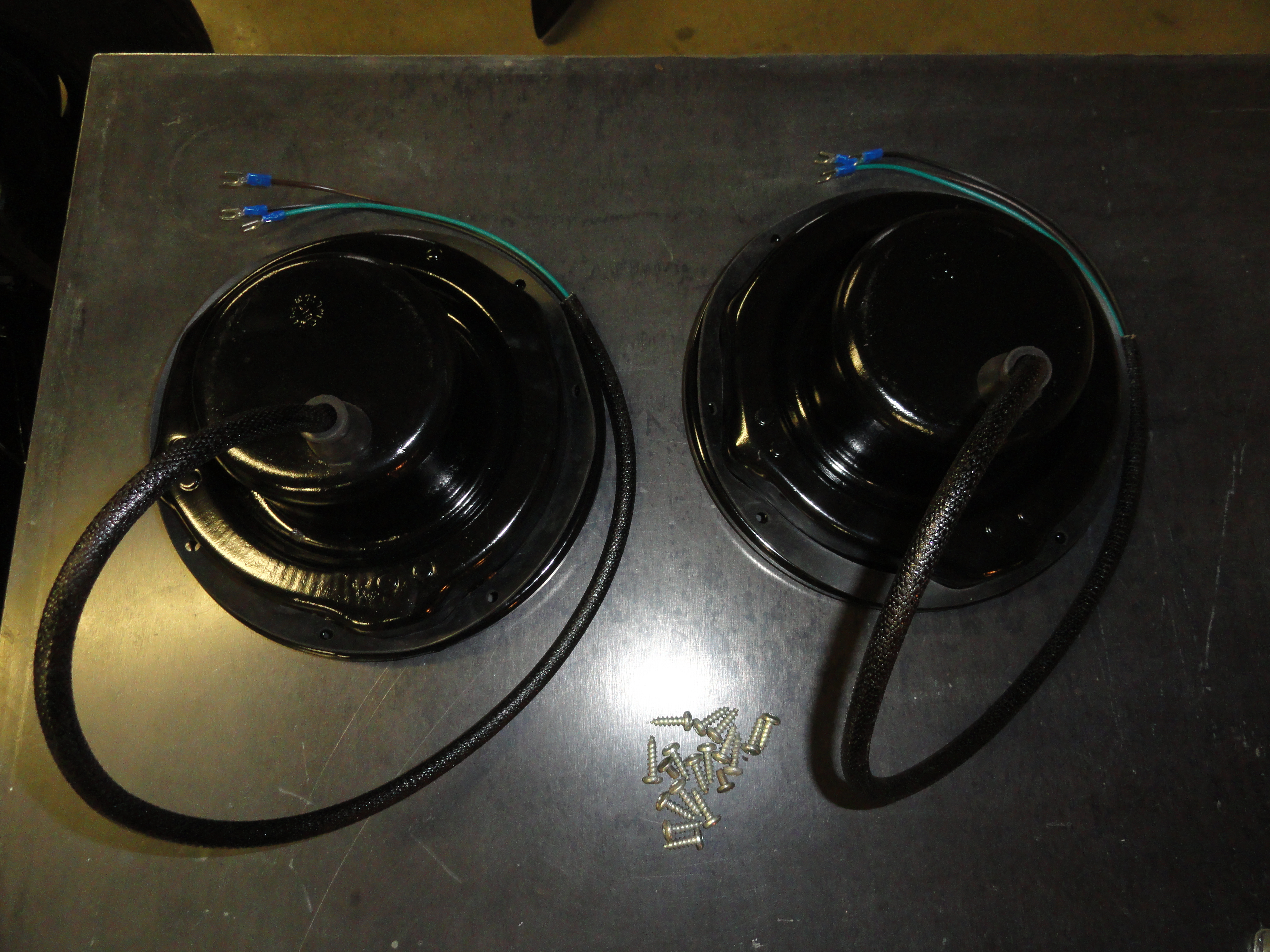
Once you have your Bucket Grommets installed, you can thread these two harnesses (one through each bucket) into the bucket from the front, with the terminals coming out the back. Now, reach through the headlight hole and push the terminal ends through the inner fender grommet hole. Replace that grommet if you haven't already. Once the wires are near the terminal blocks on the inner fender, you can install the headlight buckets and headlights. 9 sheet metal screws, two adjustment screws, a spring and a bezel later, you can now wire the headlight wires to the terminals. The three terminals are as follows:
1) Front most terminal screw nearest the headlight - High Beam
2) Center terminal screw - Low Beam
3) Rear most terminal screw nearest the firewall - Parking Lights
You will be stacking the main harness wires on top of these screws so don't tighten yet.
Step Four: The Dome Light
The reason we put this here is because we want to get rid of all of the contents of the Harness package before we go to the main harness. You will find a single wire labeled with the appropriate number for the dome light in the package. It's one wire but it's not the easiest one. This wire simply goes from the headlight switch, straight up the A-pillar right beside it and up to the dome light. Locate the old dome light wire and using electrical tape, butt them together so the profile is very thin and tape them up carefully without creating a large blob. Once they are secure, pull the old wire from the roof side and thread the new wire into the old wires position. This is easier said than done. I had some sharp obstruction that broke the line so I went to Plan B and fished it with safety wire, then did the same thing. That worked. Connect the dome light to the new wire and use those wire clips that you see clipped to that lip on the roof side. The clips I am referring to are pictured in the archive. Connect the other end to your headlight switch per the diagram on the back of page one of the instructions.
Step Five: The Main Harness:
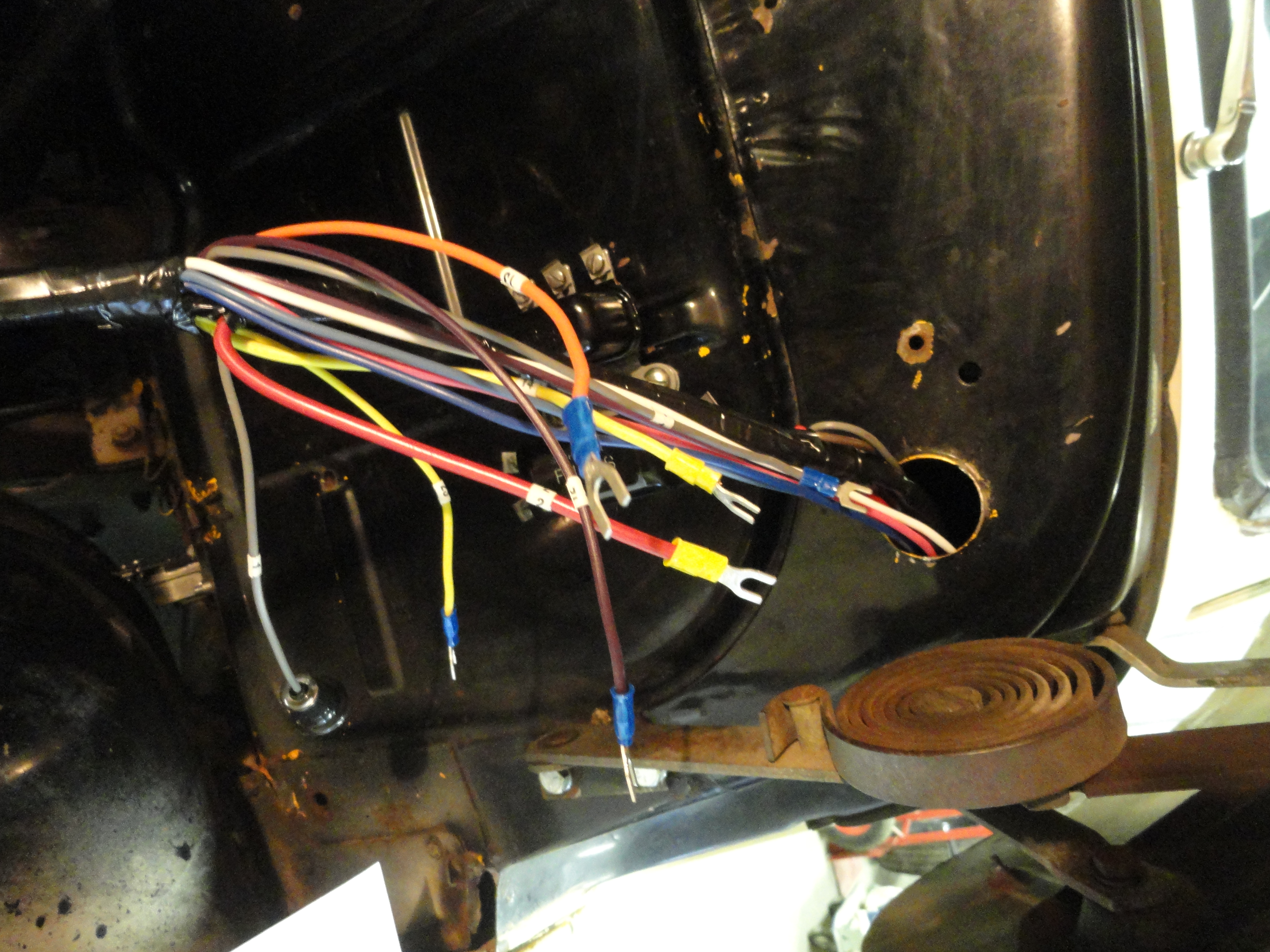
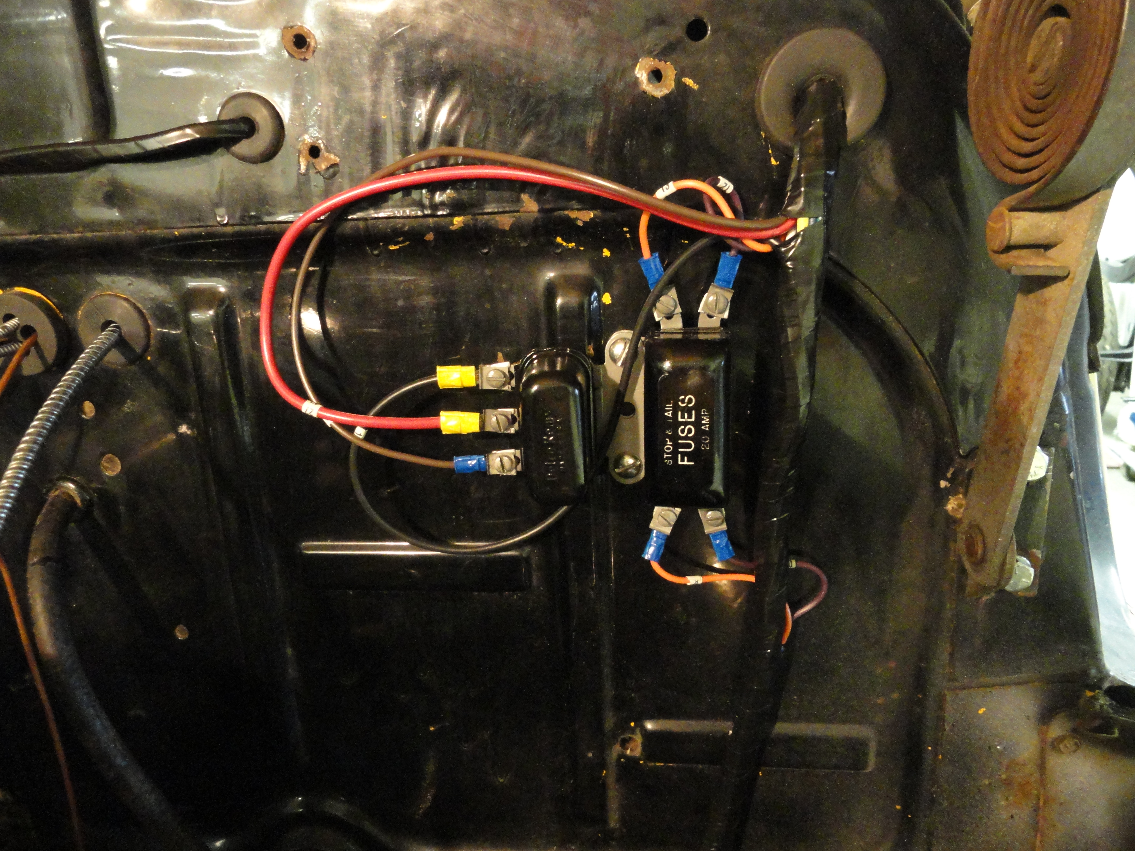 Sadly, or not, you are not going to see a lot of pictures of the install of the main harness. This is because it goes so fast, you are almost done before you get started. Spread the harness out and notice it has three main branches. One branch has gauge lights on it so that obviously goes through the main harness grommet hole. Cut your Main Grommet with an Exacto Knife so there is a slit from the center hole to the outside. Another branch will go down the firewall and get all of the electricals there, and another branch goes to the headlights. With it laid out across the fender in the proper orientation, go ahead and thread the gauge lights and all of that through the main harness grommet hole. Notice a set of terminals that look perfect for connection to the fuse block and horn relay. The wires are spaced perfectly for connection there. That is where you stop feeding through the hole. Go ahead and make the connections at the fuse block and horn relay. Rely heavily on the instructions. Each terminal has a number on it and the instructions tell you exactly where each wire goes. With the fuse block and horn relay wired, let's look at the headlight and park lamp branch.
Use those rubber Adel clamps to help secure the wires. I like to have a clamp every 3 feet or wherever the bundle gets a little stubborn. With the instructions close by, make the terminal connections at the inner fender. Do not overtighten these terminal screws! They strip out real easy! Snug is fine. Now with the harness connected for the headlights, the park lights will also require connection. I find that removing the hood latch plate assembly gets you perfect access to easily make these connections.
 Each park light has dual filaments now so you want the most dominant filament for the turn signals. You may have to experiment later and swap the wires around to get them correct to each other, so leave that area exposed for now. You need one of the filaments to go to the rear-most terminal on the inner fender. They did not supply a short wire for this so go to the bundle of extra wires they supplied and use one of those, or get some yellow wire to keep the color coding the same. There is a very convenient hole at the inner fender/radiator support to thread the horn wires and the park lamps through. The Main Harness has those connections so look over the instructions and it will be obvious as to what wire connects to what. With the park lights and horn wired, and everything secured nicely, we can move on to the lower firewall branch.
NOTE: I am not circumventing the manufacturer's instructions in this article. It is imperative that you look over those two sheets of paper and use them at each step. If I say something contrary to what they did, use THEIR instruction.
 The Lower Firewall Branch is for the Headlight Dimmer Switch, Brake Light Switch, Fuel Sending Unit, and Stop/Tail Light system. Thread this harness through the existing wiring clips down to the ground. Wire the Dimmer Switch and Brake Light Switch first. Once you have them secured and in their correct wire clips, thread the rest of the bundle down and into the driver's side frame rail. Be sure to route the bundle carefully taking into account moving levers and parts. Use Adel Clamps along the frame rail as much as possible to keep the wires secured.
Next week we will finish this 4 part series and check everything out. I am hopeful you are getting something out of this article and if there are any mistakes, be sure to let me know! Seeya Next Week!