


 Welcome to Deves Technet.com Forums. I encourage everyone to register so we can get a better idea of the traffic and its usefulness. Please leave a word or two describing your stay and what we can do to make it more enjoyable. Thanks!
 Tweet
Tweet
Replacing the Wiring Harness in a 1953 3100 (Part 4 Final):
So far we have the Headlights, Parklights, Horn, Stop/Tail Fuse Block, Horn Relay, Brake Light Switch and Dimmer Switch all wired and we are making good progress. We left off last week with a harness branch lying on the garage floor under the firewall, and the interior wires stuffed inside through the main harness grommet hole.
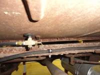
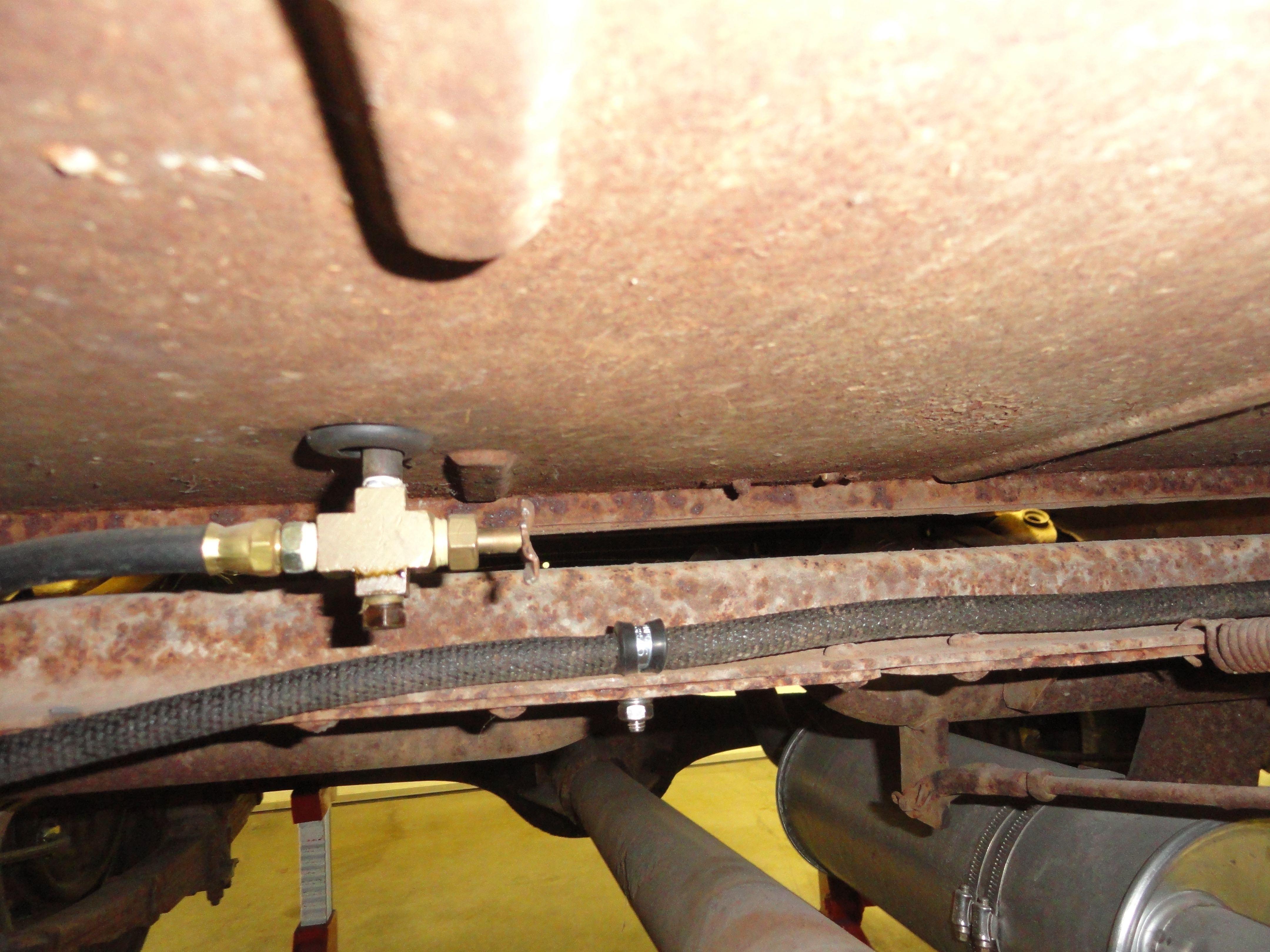
Let's finish the branch that goes under the firewall and into the drivers frame rail. It is hard to see, but there is a stock clip right where the toe board and the floor meet. Clip the wiring harness there, then run it through the master cylinder brake bracket into the drivers frame rail. Use Adel clamps where you can to keep things neater and safer. Be sure you routed it so there are no problems with moving parts like brake or clutch springs/pedals, etc. Once you are happy with your routing, the next thing to connect is the Fuel Sending Unit Wire. This is a single wire that goes through a grommet in the floor very near the fuel tank. Remove the seat back so you can get to it, and from underneath, thread the wire through the grommet where you can pull it up to the Sending Units center terminal.
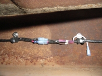
 With the Sending Unit addressed, the wires that are left over are for tail lights and rear turn signals. At this point, you will have wires with barrel connection splices on them. They will be numbered and ready for continuing to your tail light assemblies. Do the best you can to maintain color coding in adding length to these wires. If you have your 7 wire turn signal switch, one of the wires can just stop and go nowhere. In my case it was wire number 22. The turn signal switch will control the stop lamp circuit. Follow directly down the drivers frame rail for the drivers side tail light. Back in the day, you would be finished since they didn't have a passenger side tail light. I went across the rear frame rail crossmember with my wires to the passenger frame rail.
Once you get to the tail lights, there are grommets on the side of each frame rail or there should be. Install a new grommet and then thread the two wires through it to the tail lights. Again, you want the most dominant light, in this case the center bulb, to be your brake light. Open the tail light to determine the color of wire that corresponds to that one and connect accordingly on each side. That concludes the outside part of the Harness Install!
The Alternator connection has a provided plug to make everything very easy. There is the main terminal wire that goes to the Ammeter Positive and then the two smaller wires. One is jumpered direct to the main terminal on the Alternator, the other goes to the Ignition Switch. The one that goes to the Ignition switch is your idiot light function. More on that in this article: Adding a CIS. I mention this here so you know there is more fun to be had!
Now for the Fun Part!
It is not as big a deal as it looks. Work from the floor of the cab. With the gauges sitting on the floor, you can more easily manipulate the wires. Be careful when connecting to ensure you do not route a wire on the wrong side of an obstruction. Be careful and deliberate and you will be fine. Install light bulbs in each socket per the parts list. Push the sockets into the gauge cluster, two for the left cluster, three for the right and one for the ignition switch housing. The third one on the speedometer cluster must be numbered to correspond with the high beam indicator. If the wires are too short to work from the floor, let them dangle wherever they want. Follow instructions on which wire goes to which terminal carefully. The Fuel Gauge may need extra attention. If you are going to 12 volts, you will want to add a reducer OR order a new 12 volt version of the fuel gauge. The reducer listed in the parts listing will work great. Face the stripe of the Diode away from the gauge and using a round terminal on the non-stripe end and a barrel connector on the stripe end, cover the diode in heat shrink tubing to prevent a short and then install it on the power side of the fuel gauge. More information on how to do this is in another article called: Going Native!
As you can see, it's infinitely easier to make these connections with the gauges and ignition switch out. The headlight switch is the exception since the terminals all face the clusters making them easy to get to. There is no need to say much more about how to wire the dash items other than just follow the wiring instructions on page one of the Harness Install Document. They did not include a cigarette lighter wire but that would go from the top terminal (as installed) of the ignition switch to the lighter center terminal for switched or to the back of the headlight switch for unswitched. Remember those two locations so when you add accessories, it is no problem for you. Button everything up carefully. Once you are sure your terminal connections are made solid and your copper tubing is routed properly, reinstall the gauges using the 4 nuts per cluster you removed when taking them out. Install the Ignition Switch using the two 1/4" bolts and nuts. Check over everything physically to make sure everything is tight, well routed, and clean. Once the gauges are installed, it is VERY hard to get to connections, so be sure of your work as best you can.
Testing Your Work
If you were careful and meticulous, your installation will be absolutely bulletproof. Apply battery power and watch carefully for any smoke or strange noises. Then here is a list of things to look for.
This is by far the easiest Harness to install I have run across. If you follow each numbered wire corresponding to the instructions, you simply can't lose. If you do run into issues, you can usually think your way through them. This is because of the intuitive nature of the harness build. This cannot be said for all harnesses. I was impressed with the ease of the install, the Kit contents were above average, and when its all said and done, your truck is back on the road again with none of the worry about all of the old frayed wiring. Of course, small things were criticized, but in my opinion, if you didn't have to run to your local auto parts store for something small more than twice, you have a winner! If you have questions or comments about any of the information contained in this article, email deve@speedprint.com or go to Forums.Devestechnet.com and start a new thread. Good luck!
This series is now in the How-To section of the main site at http://devestechnet.com/Home/ADWiringSystem. Stay tuned for next weeks Tip of the Week!
So far we have the Headlights, Parklights, Horn, Stop/Tail Fuse Block, Horn Relay, Brake Light Switch and Dimmer Switch all wired and we are making good progress. We left off last week with a harness branch lying on the garage floor under the firewall, and the interior wires stuffed inside through the main harness grommet hole.
Let's finish the branch that goes under the firewall and into the drivers frame rail. It is hard to see, but there is a stock clip right where the toe board and the floor meet. Clip the wiring harness there, then run it through the master cylinder brake bracket into the drivers frame rail. Use Adel clamps where you can to keep things neater and safer. Be sure you routed it so there are no problems with moving parts like brake or clutch springs/pedals, etc. Once you are happy with your routing, the next thing to connect is the Fuel Sending Unit Wire. This is a single wire that goes through a grommet in the floor very near the fuel tank. Remove the seat back so you can get to it, and from underneath, thread the wire through the grommet where you can pull it up to the Sending Units center terminal.
 With the Sending Unit addressed, the wires that are left over are for tail lights and rear turn signals. At this point, you will have wires with barrel connection splices on them. They will be numbered and ready for continuing to your tail light assemblies. Do the best you can to maintain color coding in adding length to these wires. If you have your 7 wire turn signal switch, one of the wires can just stop and go nowhere. In my case it was wire number 22. The turn signal switch will control the stop lamp circuit. Follow directly down the drivers frame rail for the drivers side tail light. Back in the day, you would be finished since they didn't have a passenger side tail light. I went across the rear frame rail crossmember with my wires to the passenger frame rail.
Once you get to the tail lights, there are grommets on the side of each frame rail or there should be. Install a new grommet and then thread the two wires through it to the tail lights. Again, you want the most dominant light, in this case the center bulb, to be your brake light. Open the tail light to determine the color of wire that corresponds to that one and connect accordingly on each side. That concludes the outside part of the Harness Install!
The Alternator connection has a provided plug to make everything very easy. There is the main terminal wire that goes to the Ammeter Positive and then the two smaller wires. One is jumpered direct to the main terminal on the Alternator, the other goes to the Ignition Switch. The one that goes to the Ignition switch is your idiot light function. More on that in this article: Adding a CIS. I mention this here so you know there is more fun to be had!
Now for the Fun Part!
It is not as big a deal as it looks. Work from the floor of the cab. With the gauges sitting on the floor, you can more easily manipulate the wires. Be careful when connecting to ensure you do not route a wire on the wrong side of an obstruction. Be careful and deliberate and you will be fine. Install light bulbs in each socket per the parts list. Push the sockets into the gauge cluster, two for the left cluster, three for the right and one for the ignition switch housing. The third one on the speedometer cluster must be numbered to correspond with the high beam indicator. If the wires are too short to work from the floor, let them dangle wherever they want. Follow instructions on which wire goes to which terminal carefully. The Fuel Gauge may need extra attention. If you are going to 12 volts, you will want to add a reducer OR order a new 12 volt version of the fuel gauge. The reducer listed in the parts listing will work great. Face the stripe of the Diode away from the gauge and using a round terminal on the non-stripe end and a barrel connector on the stripe end, cover the diode in heat shrink tubing to prevent a short and then install it on the power side of the fuel gauge. More information on how to do this is in another article called: Going Native!
As you can see, it's infinitely easier to make these connections with the gauges and ignition switch out. The headlight switch is the exception since the terminals all face the clusters making them easy to get to. There is no need to say much more about how to wire the dash items other than just follow the wiring instructions on page one of the Harness Install Document. They did not include a cigarette lighter wire but that would go from the top terminal (as installed) of the ignition switch to the lighter center terminal for switched or to the back of the headlight switch for unswitched. Remember those two locations so when you add accessories, it is no problem for you. Button everything up carefully. Once you are sure your terminal connections are made solid and your copper tubing is routed properly, reinstall the gauges using the 4 nuts per cluster you removed when taking them out. Install the Ignition Switch using the two 1/4" bolts and nuts. Check over everything physically to make sure everything is tight, well routed, and clean. Once the gauges are installed, it is VERY hard to get to connections, so be sure of your work as best you can.
Testing Your Work
If you were careful and meticulous, your installation will be absolutely bulletproof. Apply battery power and watch carefully for any smoke or strange noises. Then here is a list of things to look for.
- Switch on the Park Lights. Are the dominant ones NOT lit? Flip on the turn signals one at a time. This is where you may need to swap the wires around to get the desired result. If there is a problem, refer to Step 17.
- Check the Tail Lights. Are the dominant ones lit when you depress the brake pedal? Are both sides lit properly? Check the turn signals.
- After the above passes, turn on the Headlights. Are they both lit? Hit the Dimmer Switch. Do you get High Beams? In a darkened room, turn the headlight knob. Do the gauge lights change brightness? Does the High Beam Indicator Light on the Speedometer Cluster illuminate?
- Does the Dome Light/Switch work?
- Turn the Ignition Switch to on and look at your fuel gauge. Does it reflect the amount of gas in the tank? If it is not Full and you are sure of that, but it reads Full, likely problem is your sending unit needs a short wire from one of the mounting screws to the cab ground somewhere.
- Look at your Ammeter. Flip on a turn signal. Does the meter bounce a little from about Center to Discharge? That is a good indicator prior to starting the Alternator.
- Hit your Horn button. Does the horn sound off?
- With the ignition on, start the Truck. Does it run?
This is by far the easiest Harness to install I have run across. If you follow each numbered wire corresponding to the instructions, you simply can't lose. If you do run into issues, you can usually think your way through them. This is because of the intuitive nature of the harness build. This cannot be said for all harnesses. I was impressed with the ease of the install, the Kit contents were above average, and when its all said and done, your truck is back on the road again with none of the worry about all of the old frayed wiring. Of course, small things were criticized, but in my opinion, if you didn't have to run to your local auto parts store for something small more than twice, you have a winner! If you have questions or comments about any of the information contained in this article, email deve@speedprint.com or go to Forums.Devestechnet.com and start a new thread. Good luck!
This series is now in the How-To section of the main site at http://devestechnet.com/Home/ADWiringSystem. Stay tuned for next weeks Tip of the Week!