


 Welcome to Deves Technet.com Forums. I encourage everyone to register so we can get a better idea of the traffic and its usefulness. Please leave a word or two describing your stay and what we can do to make it more enjoyable. Thanks!
 Tweet
Tweet
Note: As with all of the content on this website, you can simply click on any picture to get its largest size. In this way, we can maintain the clearest definition to make it easier for you to see the detail. If the picture is so big you can't see all of it on your screen, all you have to do is hold down CONTROL and move the mouse wheel up and down to resize!
Note before we get started...
The idea is for a group of interested restorers to create something I call 'Solution Criteria'. In other words, what do we want this project to look like EXACTLY. In this case we used the following for Solution Criteria:
3 speed floor shifters are notoriously a bad idea due to how the transmissions linkages are on the left side. Because of the location of the shift levers, most hackers just hack a hole way back near the seat pedestal and on the left side, then make a shift lever that 'works'. So here is #1 solution criteria:
a) The shifter must come through the floor in the exact same spot as the STOCK 4 speed transmission did when the truck was new.
We don't want to source out universal shifter levers for our transmission, we want to use the stock 3 speed levers in the stock configuration. Why is this so important? Because if you decide you don't like your floor shifter mechanism, you shouldn't be penalized for it. You should be able to re-attach your column shifter in a matter of seconds without worry. So here is #2 solution criteria:
b) The stock transmissions shift levers must remain in the stock orientation without any modifications.
We do not want to use a system where off-board pivots are used to accomplish this. We want the shifter to be mounted directly on the transmission and we want to feel the vibrations of the drivetrain just like you can with a stock 4 speed. So here is #3 solution criteria:
c) The solution must not have any chassis or off-board mounting parts.
4) After all of the above, we absolutely do not want any slop introduced by the solution that would make the shifter feel sloppier than a stock 4 speed. Truth be told, this isn't too hard because the stock 4 speed had LOTS of slop in it, but this solution is much tighter and more responsive. So here is #4 solution criteria:
d) The solution must be as tight and responsive as the stock 4 speed shifter.
So as you can see, this effort is different from anything you have ever seen before. The criteria is first and foremost. We do not 'settle' for anything less than what we originally set out to do. It's either everything we want, or it's not at all. This philosophy will be front and center at devestechnet.com. We are not in this to make money, just solve problems in a very productive way. Of course if someone wants one of these shifters and can't make it themselves due to shop or experience limitations, depending on availability of experienced shop experts, we can arrange to put together the resources to make one for you at no more than standard shop rates. This isn't about profits, it's about giving back to a very worthwhile community. Whatever you do, if you got this far, let us know what you think!
 Back in the day, when you went to purchase your new 1947-55 Chevy Pick-up you had two options; a 4-speed transmission with the shifter on the floor, or a 3-speed transmission with the shifter on the steering column. The three speed column shift option had its advantages. It allowed for more comfort for the middle occupant. Also, it was a popular mechanical solution and sold very well.
 But if you are like me, and reminisce about the old truck with the stomp starter and the shifter on the floor... driving down the road with one hand on the wheel, the other on the shifter.. feeling the drive-train, its vibrations, etc. all directly, then you prefer the floor shift. Not to mention, some of us gear-jammers couldn't keep them adjusted!
But alas, we have a 3 speed or 3 speed with the Borg R10 Overdrive and we still want the shifter on the floor. NO, we do not wish to put the shifter in some unorthodox location to the left and near the seat pedestal. NO we do not wish to hack up the floor and put in some universal shift kit. WE want our shifter to come through the floor in EXACTLY the same location the 4 speed of the same vintage did. WE want to use the stock transmission levers in their stock positions. WE want to purchase a 4 speed transmission cover from our vendors and expect it to work perfectly. We also do not want any off-board pivots or anything to dampen the true vibrations of the drive train. Many of you reading this are laughing because for 60 years, nobody has been able to make this happen. After-all, there is less than 1 inch of space from the top of a 3 speed transmission to the bottom of the cab floor. I hate it when people say.. 'you can't do that', don't you?
 After many hours of research, making several prototypes and lots of head scratching, here is the solution that does everything we want. I hope you feel the time to do this was worth it. I feel the same way James Smithson (of Smithsonian Institution fame) did when he said "I do this for the increase and diffusion of knowledge among men." So no patent pending here. It's all here in this document for you to make yourself if you so choose. Have as much fun as I did! Whatever you do, drop me an email telling me how you like it, what improvements we can make, etc.
The "engine" for this project is a universal shift mechanism. Basically the top part or head of the unit. It's a bit expensive to create your own shifter mechanism and I didn't feel like re-inventing the wheel, so go get yourself a Hurst shifter kit [part number HUU-5010016] for about $225.00 OR a Mr Gasket shifter kit [part number 7667A] for about $50. They both work equally as well and require the same modifications. The only reason I mentioned the Hurst offering is because I purchased that one first.
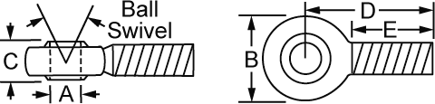
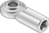 The thing that makes this all possible is the Heim joints. The Heim joint is a ball and housing that rotates bi-laterally as shown below. We don't care about the threaded part, so the female ones work just a little better than the male ones because the cutting area is more emphasized.. Then, you may find uses for the threaded part for other projects!
So now I will try to explain what is happening here. We have virtually NO room to work with, about 3/4 inches at the front of the transmission and about 1-1/8" near the back of the area in question. The driver's side of this mechanism is very straightforward. The linkages end up meeting exactly where we want them to. But the other side is another issue altogether. We need to move the action from the wrong side of the transmission to the left side. To do this, we will use a 3/8" shaft (12-1/4" long) with two small bearing assemblies with housings. This also then puts the linkage in just the place we want it. Easy peasy right?
 In case you are more of a genius type and are asking yourself why two pivots on each side instead of a much easier single pivot point, it's because doing that reverses the shift pattern. Not only do I want all of the features I outlined earlier, but I also want the shift pattern to be standard. Here is what your transmission's levers are doing:
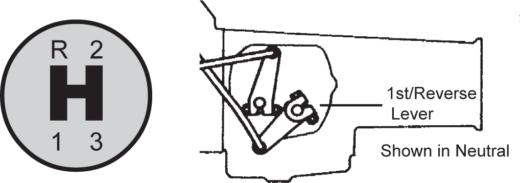
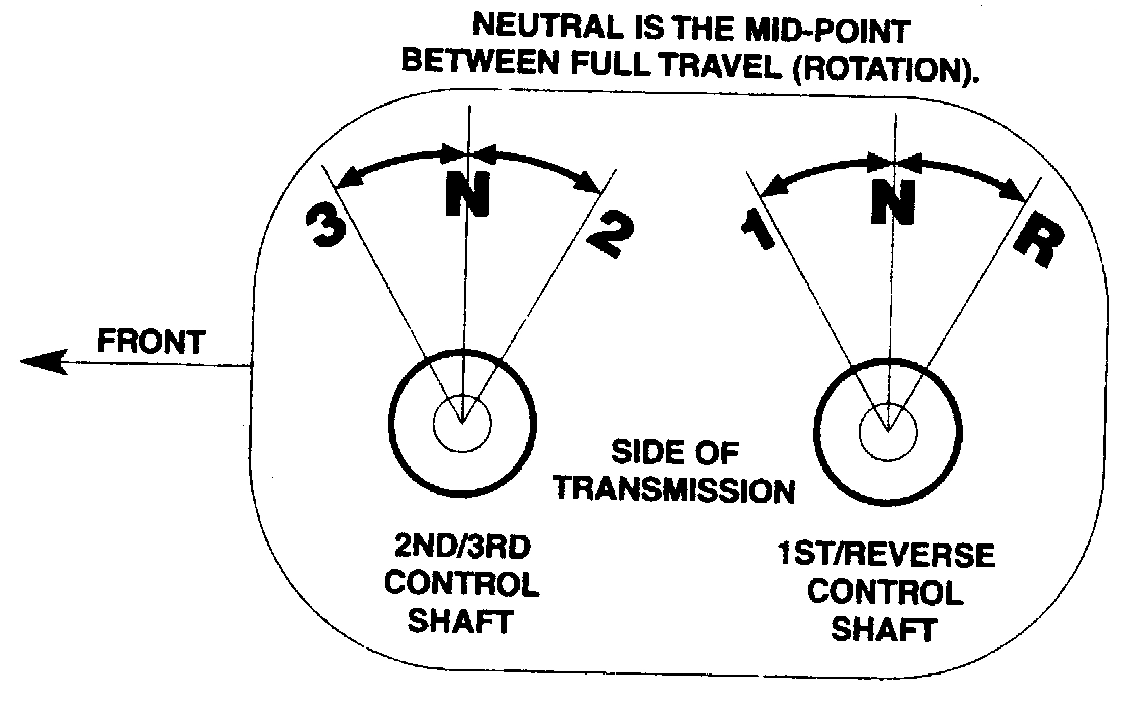 So, a single pivot would make it shift backwards. Another consideration that is quite important to the success of this project is that the truck's shift levers need to be standard, and in the stock location. If you have changed your shift levers from stock, change them back! Some of the readers of this document will want to shift a Borg R10 Overdrive unit. No difference from the 3 speed except that the Borg R10 was not original to the truck, and the transmissions shift levers may not be in the place they should be. The RIGHT way to resolve that is to get a side plate from an original 47-55 3 speed transmission and replace the shift lever assembly. The other reason for doing that is if you ever want to put a dual MC on your truck, your incorrect lever shafts will interfere. Ask me how I know! Another way of course is to get two universal shift levers and just point them in the right position. Here is the correct placement. It's from the shop manual.
So now that you have your shift levers correct on the transmission, and your 4 speed transmission cover, you are ready to tackle this pretty involved but very satisfying project. Understand that I did all this with very rudimentary tools as far as metal working tools go. You will want to make friends with your local welding/machine shop because there are things they can do for you to cut down on the approx. 160 hours of time it takes (equiv. to one full week) of labor if you do it all yourself. We aren't whistling dixie here folks.. it's quite a project. But imagine how you will feel once it's done and works exactly as advertised. Nobody, and I mean virtually nobody has this setup on their truck, so the satisfaction that you will feel pulling this off will make it all well worth it!
Tools List:
As I said earlier, I don't have an unlimited tool budget. I use what I have. So if you have better, consider yourself fortunate. If anyone has a free Laser system they would like to donate to a good cause, I am your man!
There are times in the drawings I use the next size higher drill bit. Instead of 5/16" I might specify 21/64". Other times I may not. This is by design. Please use the specified bits so that you don't end up with slop. Slop is a shifters equivalent to the devil. We are doing everything I know how to prevent slop and give you a very clean shifter.
Shifter Fact! Most people do not realize that when you disconnect your shifter from the transmission, it just dies. Just like a robot that gets shut off. No detents, no clarity in its purpose, just slop, slop and more slop. It's the transmission that FULLY provides you with a clear Neutral, and gear system. The shifter does nothing except organize your shifting into a pattern. My first attempt at this design, I had installed special detents to further emphasize Neutral so there was a clean, concise difference. It failed because it's not needed, nor desired.
Parts List:
 Metal is expensive, but what I do for my projects is to get used, repurposed, or small cutoff pieces from a local welding shop scrap pile. I will list the metal and sizes you need here. You cannot get a single piece for the frame of this project for mechanical reasons, so please follow the list carefully. There will be a reason for everything.
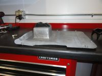
Since we are making parts from scratch, this may seem daunting, but it's not really that hard if you have the Tools in the list. Let's start with the 10 inch wide by 8-3/8" long, 10 gauge plate. There are full size templates at the end of this instruction.
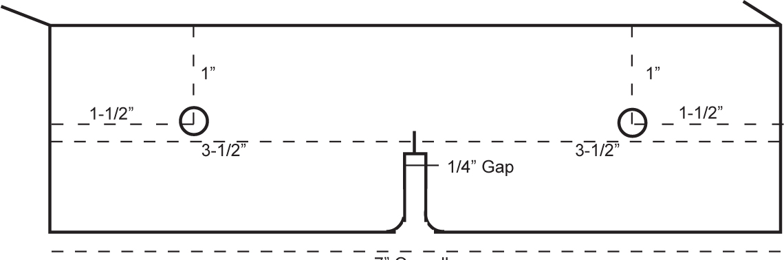
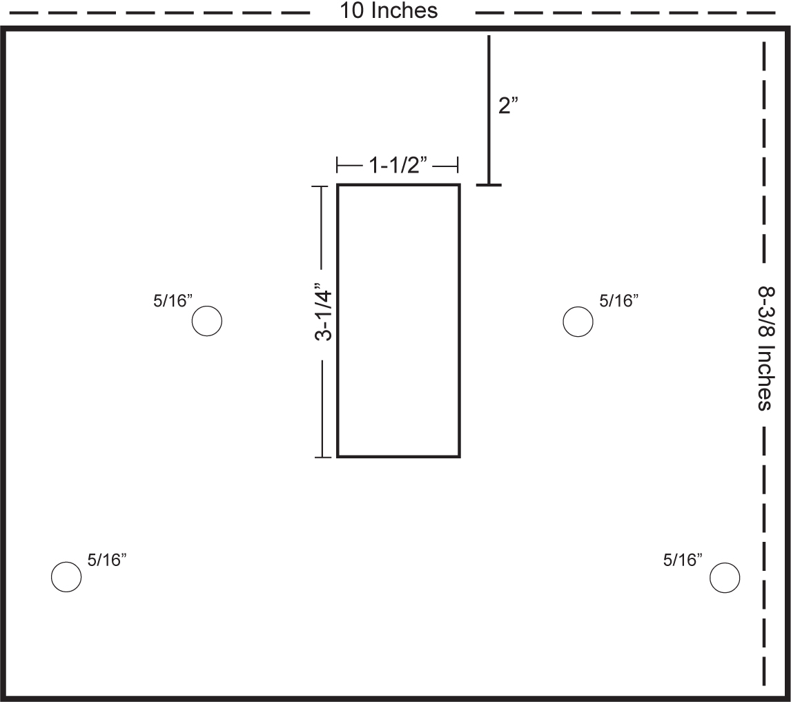 The hardest part of this plate is cutting out the rectangular hole. The hole is 3-1/4" by 1-1/2". It is placed in the very center of the 10 inch dimension, so measure and put a mark at 5 inches, then go 3/4" to each side. For the 3-1/4 inch dimension, measure from the top, 2 inches down, then start the 3-1/4" per the template at the back of this manual. This should be as precise as possible. I used my 4 inch Makita grinder with thin cutoff discs, then finished the corners with my Dremel tool with 1-1/2" thin cutoff discs.
The two 5/16" holes adjacent to the cutout must be exactly centered on the 3-1/4" opening. This serves as the primary center pivot. Drill the holes 4-5/8" from the bottom, and 2-5/8" from each side.
The other two 5/16" holes are 3/4" from the sides and 1-1/2" from the bottom of the plate. Try to be as precise as possible.
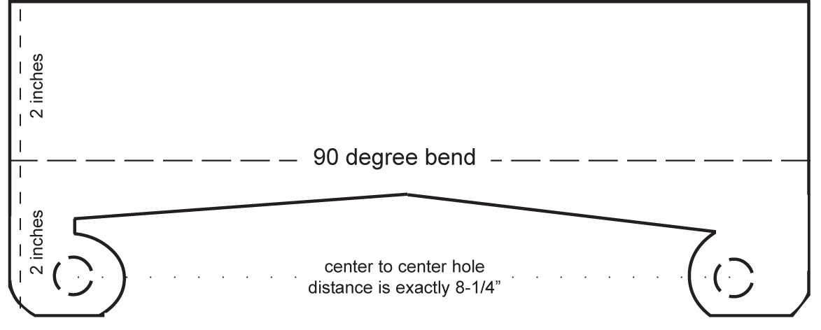
The next step is to make the front piece. This is simply made with 1/8" x 10" piece of angle iron. There will be some trial and error here. This is why I provided the actual size templates at the back of this document. It will not be perfect, but it will get you there. The reason for it not being exact is because the cast housing of the transmissions are all slightly different but mostly due to the precision of your work in sculpting this piece. The front and rear pieces are the hardest part of this.
Be sure to sculpt the correct side. Concentrate on the straight lines first. This is where the porta-band with table really comes into play. Once you have it all marked with your sharpie, just do whatever gets you there! Marking the back side of the angle iron is the most difficult. Be sure to do your diligence in measuring and marking before you make your cuts. I suggest drilling the two 1/2" holes first. Make sure you use a good punch and measure exactly 8-1/4" between the two holes and 7/8" from the edge to the center of the hole. It's important to get these two holes exact and balanced so that the plate mounts perfectly straight. The holes are also 1/2" from the bottom.
 For the rear piece, we use another piece of 1/8" x 2" x 10" angle iron this time with a twist. It would be really nice if we could get 2 x 2-5/8" angle iron, but since we can't, you will have to add a 3/4" strip to one end. Since we are using 10 gauge for the top plate, we can also use that for this strip. Be sure to bevel the ends before welding to add strength and ensure a very nice flat weld. The left and right 7/16" holes are NOT exactly across from each other, so be sure to measure carefully.
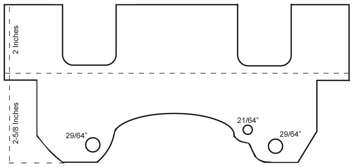 NOTE: This added strip, the holes and some of the contour can be eliminated if you are doing this for a standard 3 speed stock transmission. This piece must be precise for R10 Overdrive units only. Read this document in its entirety before starting so you are familiar with the why.
I just welded the strip all the way across so there were no worries about getting it placed right. Both diagrams are outside views. (the bend is nearest you).
Anytime you are doing custom work of this sort, patience is a virtue. Just like with the front piece, lots of sculpting here. Be very careful to measure properly when to transferring the template to the back of the work for cutting with the bandsaw table. Cutting the holes first will make it easier and more flat in the end.
Ok, so you have the main parts made and now we need to assemble them. Are you familiar with a technique called spot welding? In case you are not, it's just drilling about 7/16" holes every so often in the angle iron only, then weld through the hole to fix the two pieces together. So, get to it! Drill about 4 holes at intervals that make sense and do not interfere with the workings. Take a look at the pictures on page one and do your thing! But, education is always first, so, before you just haul off and weld stuff, bolt the front piece to the transmission/bell housing connection and check that your bolt holes, sculpting, ect. are dead on. If they are not, don't feel bad, just use your Dremel and change the configuration a bit to match your system.
Once you have the front bolted on and it's all tight, bolt on the back and see how it looks. It should be centered on the transmission and front piece and it's a simple matter of placing the top plate on and it should all be perfectly square. But even better than getting it square, put a level on it (front to back) and it should show perfectly level from front to back. This is needed so we have the room we need to add the mechanical parts. Don't get too bent out of shape if it's a little off. It won't matter. If you are an 8th off, no worries. If it bothers you, fix it! The template was designed to make the entire platform perfectly level from front to back, and left to right.
Important. Once you have it bolted to the transmission, take a few vise grip clamps and clamp it down hard for welding. Then it's all a matter of a nice clean installation.
NOTE: I am describing the rear piece as something that bolts to the transmission. Of course you see the fallacy of this if you do not have an overdrive. But, it is all still very valid because the sculpting you did will sit on that "spine" that is front to back on the stock 3 speed and be just as level. So, if you have the stock 3 speed, just bolt the rear piece on to the very edge of the top plate as you expect it to, and move on. There is a nice stock 3 speed bracket in this document but we are not there yet.
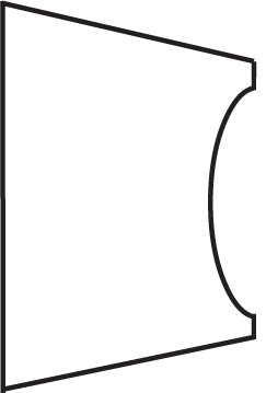
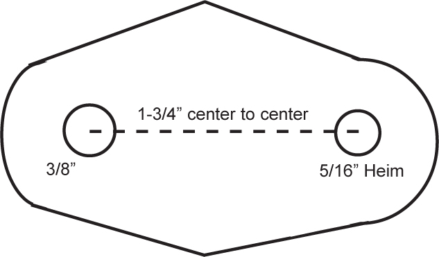
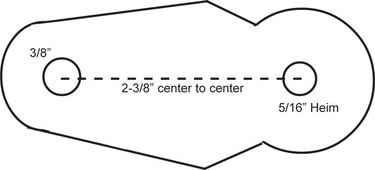
 So, now we have a tower and a Hurst or Mr Gasket shift mechanism to contend with. It was just easier and more economical to use what is already there. No sense in re-inventing the wheel. I suggest going with Mr Gasket since it's cheaper by about $200. They are similar, but they are NOT the same. Where you pay even more for the Hurst is when you need to bend the shifter mast differently. The Mr Gasket bend is less radical. This is due to the offset levers they use in the mechanism. Here is the difference, or check out the templates in the back.
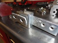
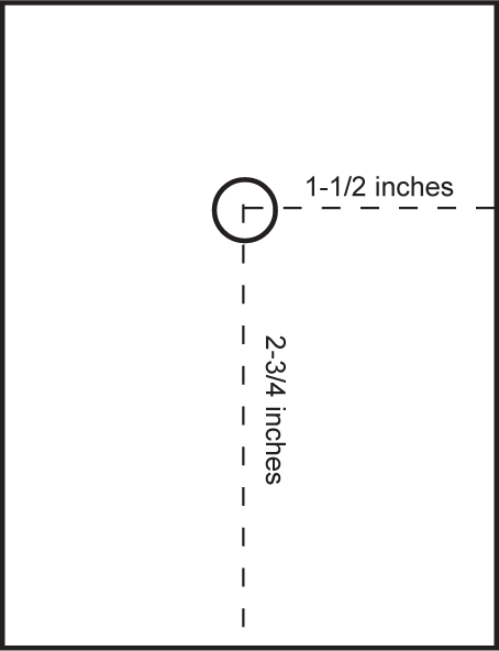
 (Left to right: Mr Gasket, Hurst) Since this is a solid design, we can accommodate both with minor adjustments. So let's make the tower bracket to fill that 3-1/4" by 1-1/2" hole you labored over in the top plate. Using 10 gauge steel. Cut out two pieces that are 3 inches by 4 inches. The hardest part of this procedure is trying to get the center hole at the proper height for the lower mechanism to meet up properly. There are two issues we are concerned with here. One is proper hole height, the other and opposite issue is the Heim joint lever length that corresponds to the hole. So let's take the hole question out and just place it at exactly 2-3/4" from the bottom.
I am making a point of this for a reason. Drill this 3/8" hole in the very center of the 3 inch (1-1/2") dimension and 2-3/4" from the bottom. Make two of these:
 Note: If you have the mechanism in front of you, the center pivot bolt will go through the holes in your two plates. Best to drill the holes together so they are exactly across from each other.
Take the mechanism, and install it between your two plates. Of course the center shifter bar goes UP and the pivoting assembly goes down. You will be removing this assembly several times, so don't expect anything permanent yet. With the mechanism installed and both plates straight with each other, set this assembly on your top plate. It is not designed to go IN the hole. It's designed to set exactly over the hole. Use those special welding magnets to hold it perfectly straight. Check and recheck this before welding. Now, important, the front of the assembly must be exactly 2-1/8" from the front of the mounting assembly. This puts the mechanism in about the center of the hole, maybe a little forward. This puts the shifter right in the middle of the 4 speed transmission cover. Once you understand where it goes.. hopefully I described it so it makes sense, weld the mechanism to the top plate. Weld on the outside and top side only!
Now you have two plates welded to the top piece that hold the shifter mechanism. Sadly, the two levers will need to be removed and modified so get used to lots of removing and reinstalling these parts. There is no need to mess with the spring, center pivot pin, or main shifter bar. Go ahead and remove the two lever bars from the mechanism. You have the pictures to the left to help you with putting them back together. Now we will do one of the more intense modifications. The two levers will need Heim joints welded in to replace the two holes at the bottom. Here's the thing. Remember the big deal I made about the center hole (above)? Well, this is critical that you get those Heim joints to the proper length to go down below the plate, but not so far as to hit the top of the transmission. We are talking about Nths of an inch here. It must be very precise.
For me, the hardest part of this project after sculpting the front and back is getting these Heim joints welded in properly. To prepare for doing this, let's get all the Heim joints prepared for the project. There are 8 of them and they all need a little preparation. We want to remove the female thread portion and be left with exactly 1 inch of just the center part. I did this with my Porta-band with table and it was relatively easy. Try not to overheat these pieces. It is possible to warp the mounting for the center ball causing them to hang up. Use a Makita grinder with a 120 grit flap disk to smooth the work and eliminate sharp edges. The Heim joints with the female threads have a distinct crease at the one inch mark so thats why it's just easier to get the female ones. Do all 8 while you are at it.
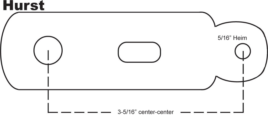 This is the Hurst shifter forks dimensions when you are done. In the case of the shifter forks, you will need to further grind off the "bottom" after they are in successfully. Notice you have two holes on both Mr Gasket and Hurst models at the bottom. We won't use the bottom one at all, and we are replacing the top one with the Heim as shown.
Make two of these exactly the same. The Heim joints are centered on the shifter forks. In other words, looking at it from the side, it should be the same on both sides.
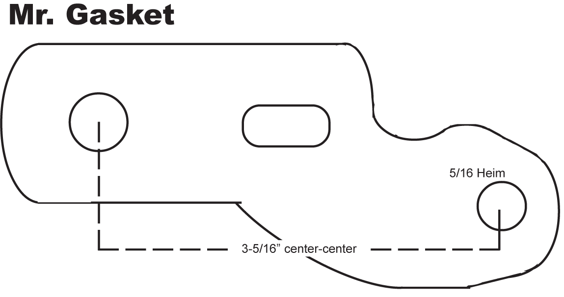 This is the Mr Gasket shifter forks. Although they look different due to the offset nature of them, the dimensions are the exact same. The advantage of going with Mr Gasket is that the offset causes the shifters mast to favor the space inside your truck a little better. But it's not a huge deal since bending the shifter mast a bit more is an option.
NOTE: Don't forget about the full size templates!
 The only difference at this point is the shape. The 3-5/16" between the holes is the very same. This shape is a plus because it moves the shifter mast more forward. With the Mr Gasket shift mechanism, we need to make a few 20 gauge plates that came with the Hurst shifter mechanism but didn't come with the Mr Gasket one. Cut two pieces of 20 gauge 3" by 2-1/2". We place these on the outside of the Mr Gasket mechanism, but inside our 3" by 4" tower. Place them at the top inside of the bare tower without the mechanism installed. Mark the tower holes and drill a 3/8" hole for the mechanism in both of them. As shown.
The Hurst shifter comes with this, but the Mr Gasket one is really more suited for our purposes, so it's a small price to pay just to add these two plates. Once you have the plates made and tested to fit, spot weld them in so you never have to worry about them again. The reason we are doing this is to allow the shifter arms to move more smoothly. If you are REALLY lazy, you can fish in some washers in between the mechanism and the tower hole that will do the same thing. I find it a hassle since you WILL be removing the mechanism more than once.
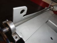
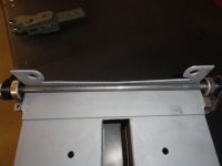
The last thing we need to do to get the framework completed is to put two 1/2" angle iron pieces that are 2-1/4 inches long near the front to accommodate the two bearing housings. The best way I have found to do this is to make the 3/8" shaft and assemble the bearings first. The 3/8" shaft rides inside the front corner of the frame. In order to weld the two angle pieces on the frame, we have to make sure the shaft very freely rotates in place. Cut a piece of 3/8" round stock that fits the bearings and bearing housing you purchased from McMaster-Carr. Test fit the bearings because it has been my experience that some so-called 3/8" round stock is too thick. The length is 12-1/4". We will need to make two thin slots for e-clip keepers that make sure the shaft doesn't try to wander once its all together. I got this e-clip storehouse collection from Harbor Freight and used the 5/16" ones. So how I made the groove for the e-clip was to carefully rotate the rod in the prescribed locations against my porta-band saw. You can do a really nice job of it once you get the hang of it. Might want to do some practice runs before trying to do 2 of them on this 12-1/4 inch rod. Cut one slot 3/4" from each end. Go ahead install the bearings inside that 3/4" and then install the e-clips.
Look carefully at the pictures to see how to weld the 2 pieces of 1/2" angle iron to the assembly. A good idea is to mark the holes from the bearing housing onto the 1/2" angle iron and drill the two holes, then grind away the shaft area (center) so the shaft moves freely when installed. Dry fit the assembly to make sure it will rotate VERY freely. What I do is wrap painters tape around the shaft about 2 inches from each end. Wrap about 6 times. The idea is to get some amount of stand off so the shaft moves freely.
Once you have both the angle iron drilled and ground to allow for free shaft movement, and the shaft mounted to the two angle iron pieces, push the shaft as far inside the front top corner as possible (the tape will be removed giving you clearance), align the two angled pieces for welding. Make sure the angle iron is perfectly parallel to the top of the frame assembly. Weld on the bottom side and on the ends so it looks nice and is sturdy as well. Remove the tape and your shaft should do two things. It should rotate very freely and it should not be removable (the e-clips are holding).
NOTE: Now is a good time to think about cleaning and painting the housing assembly before we start installing the mechanicals. A decent etching primer and a decent spray can of your choice will do. Just don't embarrass everyone with a weird color!
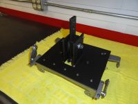
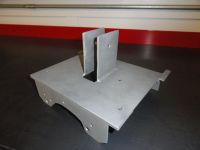
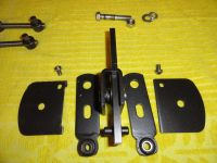
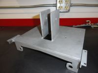
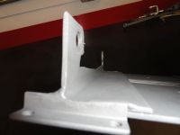
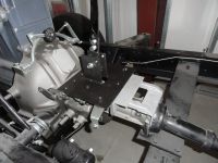
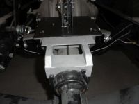
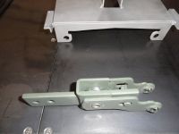
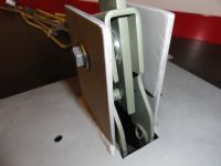
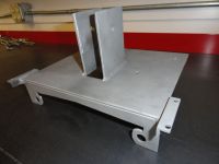 Now to get to the mechanicals. By now you have an assembly that looks something like this:
Congrats because that wasn't easy! It's all downhill from here!
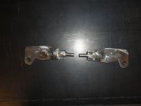
Let's begin with the primary pivot. This is the hardest one to make and does most of the work. The reason for a primary and secondary pivot is the shift pattern. If you try and cut to the chase and use just one pivot you will be as disappointed as me when I made that mistake in learning all this! You really want this shift pattern to be standard. So this is what the primary pivots look like. There are two of them, one on each side. The metal work is identical, however the 5/16" round stock we use will need to be opposite each other. It will make sense here soon...
Primary Pivots
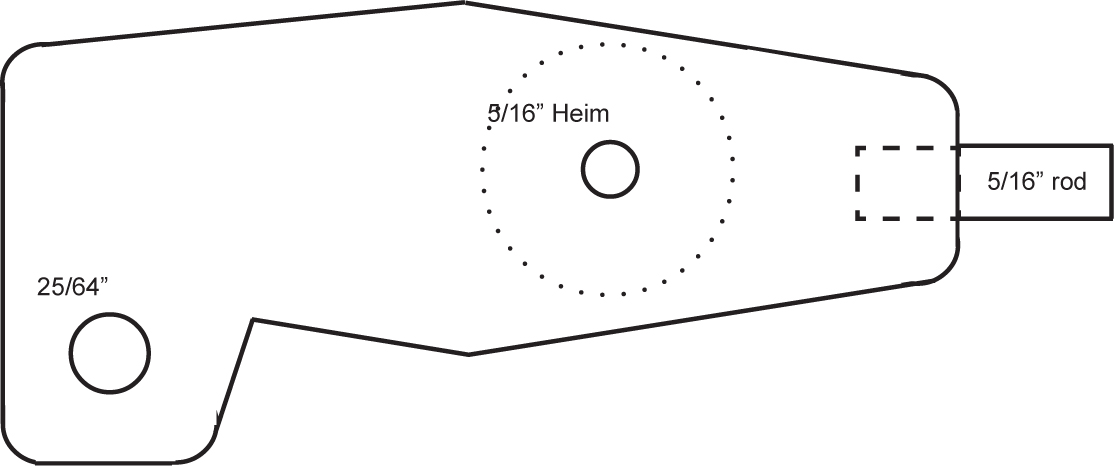 If you followed the instructions, you have 6 more Heim joints each about 1 inches round. It's important for these pivots that we use a little thicker stock to cut them out of. I chose 5/32" mild steel plate. It's just a little thicker than the 10 gauge we used for the frame yet thin enough to actually fit between the top of the transmission and the top plate. The pivots are cut into a sort of dog leg design so that later, when you are making final adjustments we can get to the clip we need to pull for adjusting the threaded rod. Here is what they look like. Don't forget to use the full size template to cut them out.
Right is a picture of the side view. There are two of these in this assembly and they must be opposite each other. What makes them different is the 5/16" rod placement. This is critical to proper movement.
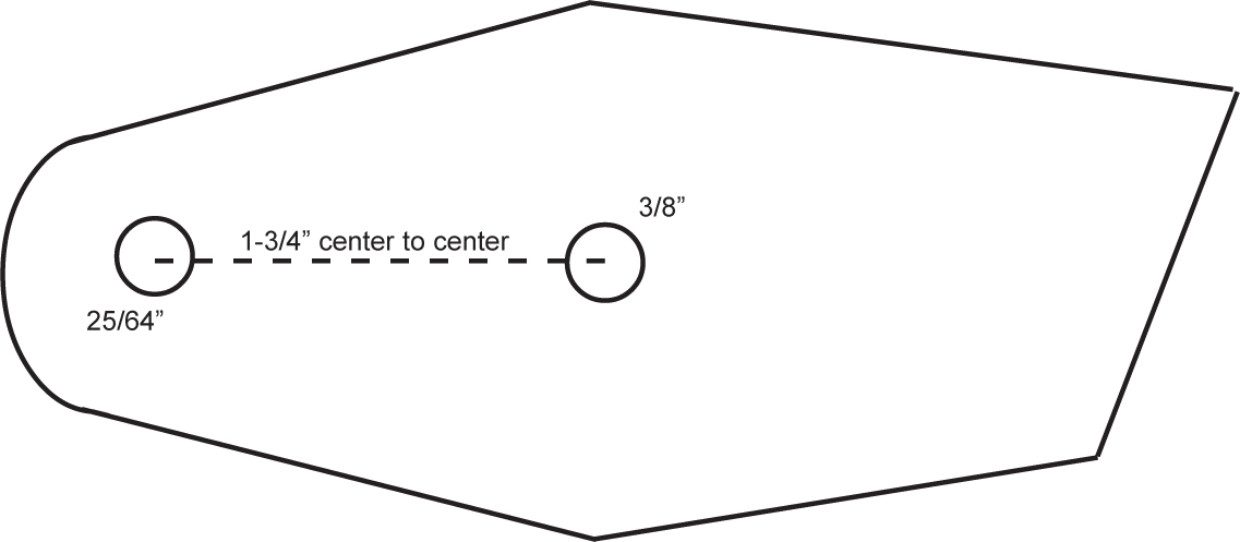
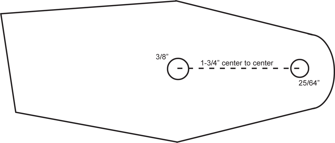
 Cut out your pivots using the template. Cut two of them that look identical. From left to right, the dimension is 4-1/4". The exact dimension between the two holes is about 2-3/8". More importantly, the edge of the rod end to the hole must be 1-1/2". Mark the center of your hole where the Heim joint goes. Use a center punch to mark it, then with a 1 inch drill bit and a good vise or something to hold it really really good, put BOTH of the pieces in together and drill them both at the same time. Be sure it's very tight in the vise because a 1 inch hole is pretty large and hard to get precise. Once you have the 1 inch holes drilled, place the Heim joints in the hole. Tweak them by grinding until they fit properly. The two pivots you are making are the same as far as how to fit the Heim joints. They should be centered exactly so that they protrude equally from each side.
Now before welding the Heim joint into place, drill the 25/64" hole (slightly larger than 3/8") for the adjustment rod. Do this together the same as you did for the 1 inch hole. This ensures you have a nice equal set of pivots.
Weld the Heim joints in place with the proper heat for a good weld, but keep things cool and weld slowly so you don't warp the bearing housing of the joint.
NOTE: Any time you turn the ball bearing in the heim joint and it doesn't move perfectly freely, it's because you slightly warped the bearing housing. To fix this problem, very carefully lay the pivot over a vise with the jaws open about 1/2" so the ball and housing are not touching the vise jaws. Wrap the ball with a hammer lightly to bend the housing back into shape. Flip it over if necessary and repeat. Do this just long enough until it rotates freely but is still very tight in the housing.
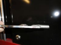
 You are almost there. Let's address the ends that contain the 5/16" rod. Cut two pieces of 5/16" solid round that are 1-1/4" long. On the pivot, measure the end with the rod and CENTER the rod on that dimension. With your trusty sharpie, mark the rod location 1/2" into the pivot so that the OTHER 3/4 inches is outside the pivot footprint and centered on that end. With a makita and cutoff wheel, or equivalent, cut enough meat out of the pivot end so that the 5/16" rod completely rests ON the table on one side, and sticks up on the other as in the last picture on the previous page. A good 3/4 inches is very necessary sticking out. Do this on both pivots. Set them side by side but OPPOSITE as shown.
They must be opposing each other and have the rod protruding upward on the proper side. The protruding rod must be 3/4" and be cleanly welded so that the entire 3/4" can be used. Now that you are ready to weld, clamp the rod down to the table as well as the pivot so it's positioned correctly and go for it!
Secondary Pivots
So that was easy right? I had lots of trouble with this part on the proper angles but now that I have it down, there is an easy way to do this.. USE THE TEMPLATE!
 The left and right ones are slightly different. The profile of these pivots are exactly the same on the end with the hole, through the middle. Just the last angle is different. Once you have the shapes all cut out using 5/32" plate stock, and the two downward facing pieces which are identical cut out, you can begin the welding process. But first drill the holes in the secondary pivots. The outside hole is 25/64" (slightly larger than 3/8"). The inside hole is 3/8". Follow the template instructions carefully. Next, weld the small piece that will hold the Heim joint on top of the long pieces following the angle that you cut in them.
 This is the part of the pivot that points downward. It works the same on both sides. Weld this piece along the edge of each pivot following the angle. Weld this piece on top of the other piece. (see Note) If you want, you can weld the Heim joint on first, but I found it easier and cleaner to weld the Heim joint last.
 NOTE: So are you having trouble deciding which is the bottom or the top of the pivot so that you don't weld the downward assembly on the wrong side? Look at the picture on page 1. THAT picture is how I decided which to call left and which to call right. Hope that helps!
So, now that you have them welded, and the Heim joint welded so that it's exactly centered, equal on both sides, you are ready to move on to the last two Heim joints, on the rod that goes across the assembly.
Bearing Pivots
So far you have the 12-1/4", 3/8" rod, with e-clips 3/4" from each end, the bearing housings and rod assembly mounted to your frame. We want to put the last two pivots on the ends of that rod. The shorter one goes on the right side of the transmission. This helps to shorten the throw a bit.
 The right side pivot's overall dimension is 2-3/4" left to right and 1-1/2" top to bottom.
Both of these pivots have 3/8" holes that will be welded to the ends of your rod assembly. The 5/16" Heim joint is welded like everything else so be sure to adher to the center to center dimension and make your cutout on that side accordingly. Set the right side (depicted above) to the side for now.
The left side is made so that it just barely clears everything without touching clutch pivots, bell housings, the other linkage, etc. This being the case, follow the dimensions carefully.
 To the right is the left side representation. As with all of these pivots use 5/32" plate and be sure to adhere to the center to center number. These numbers are important to keep the throw within limits. Overall Dimension is 3-1/2" left to right and 1-1/2" top to bottom.
Once you have the bearing pivots done, you can go ahead and weld the longer one on the left side. Slide the pivot on the rod so it's flush with the end and weld it solidly on the rod.
The shorter bearing pivot needs to be placed in one particular location. Think of a clock face. If the longer pivot is faced up and pointed to the 12 o'clock position, the smaller one must be at the 2 o'clock position. Easiest way to explain it! Go ahead and weld that one on the same way. Flush at the end. When I weld these, I only weld them on the outside. That way if something happens that I don't know how to tell time, I can just grind off the front weld and start over. Not a bad idea to temp weld one side until you are happy with placement. Are you starting to feel like you are making progress?
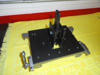
Stock 3 Speed Transmission Mount
This isn't normally the case, but in THIS case, it's actually easier if you have an Overdrive. Reason being, you are ready for assembly and testing at this point. But if you have a stock 3 speed trans, we need to build an add-on bracket for you. Here is how I did that.
 We need to extend the frame so that we can get this thing bolted up nicely. To do that, we will use the top two bolts on the torque tube connection. As with the front bolts, you can re-use the ones that are already there.
Start by cutting two lengths of 1/8" angle iron just like the frame. Cut one that is 7 inches long, and another that is 5-1/4 inches. The long one mates with the rear shifter frame. You will be putting two 5/16" holes in the rear shifter frame once you mark them. You need to mate the two angle iron pieces flush with each other. NOT flush with the top plate! This makes the 2 inch drop just about right for straddling that spline on the 3 speed trans. Our goal here is to make the shifter mechanism level to the ground in all aspects.
 If you place a level on your shifter mechanism in both directions, our goal is to make it level. Bolting these two pieces as described will get you close. Now cut two lengths of 3/4" square tubing 4-7/8" inches long. These support runners are just the right size to make a nice clean step-down to the torque tube. The front angle piece looks something like this when you are ready to weld on the runners.
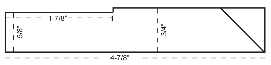 Mark the angle iron for placement of the runners. We need to do some surgery on the runners before welding. Here is a side view of the runners.
The angle at the right end is more to make it look better than anything. You can either slice the ends with a grinder and fold the top part down to form the angle, or cut it off at a 45 and add metal to fill the hole. The important thing is that the bottom is exactly 4-7/8". This is a critical number because of the placement of the bolt holes on the back of the transmission.
Place the runners so that the left hand runner is inset from the front piece by 5/8". Look at the picture opposite for clarification. The right hand runner will be inset from the front piece by 1 inch. I find it easier to wait until the back piece is made and we can clamp/level everything on the trans before welding.
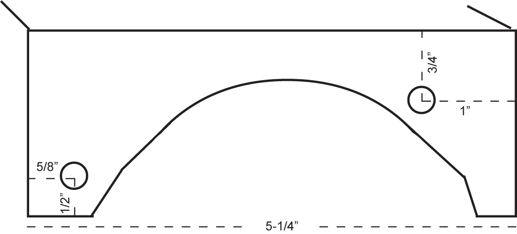 StockMountBack.jpgThe back piece is made to curve around the torque tube and use the top bolt holes. This is another sculpting job. Start with the bolt holes. They are placed as in the drawing.
Follow the full size template. Once you have the sculpting done, and everything looks right, now is a good time to go ahead and bolt the back piece on and check for fitment. Once you have it fit properly, bolt the main shifter frame to the bellhousing bolts tight, clamp the front piece described above on to the main shifter housing. Remember the two angle irons are opposite each other and level with each other, not the top of the shifter housing. Once you have everything test fit, install the runners as needed and make sure everything aligns properly. Clamp as needed or spot weld as needed to keep your alignment. I never said this was going to be easy! Once you have it aligned and ready, weld together permanently.
Now that you have seen every aspect of this project, and you followed my recommendation that you read everything in this guide before starting, you can go back and determine what YOU need for building this permanently. If it's for a stock 3 speed for example, you know you don't have to do ALL of the sculpting on the back of the main frame.
What sticks out to me as being very important that I haven't emphasized yet is the VERY limited space there is below the floor of your cab and the transmission. If you get this wrong in the slightest bit, you won't get your floor cover on. Please observe the importance of this when making the parts for this project. Follow the templates and you will succeed. At the very front of your shifter mechanism, there is less than 7/8" under the shifter frame. In the back it gets better and to the sides it gets better. Use a level to make sure your frame is level with the (flat) ground front to back and side to side.
Assembly
 To assemble the shifter tower mechanism, install so the spring is on the left with the assembly facing front and if using Mr Gaskets mechanism, the arms are pointed as shown.
Slide the assembly into the frame tower carefully observing the above and place the 3/8" through bolt through the tower assembly. Use a split lock washer and snug it down, but do not over-tighten. The two bars with the Heim joints should swing with almost no resistance.
Turn the shifter frame assembly upside down and oriented as shown on page 1.
Installing the Primary Pivots
Install the primary pivots (center ones) by using 5/16"-18 bolts as described in the parts list Number 15. Put the bolt through the Heim joint, then on the back of the pivot, place a special Heim washer on the bolt so that it extends it's ability to rotate as in parts list Number 11. Place the 5/16" round shaft in the pivot through the shifter towers Heim joint first, then place the bolt with the assembled pivot parts through the center hole. Use a lock-washer and low profile nut to tighten. Of course be sure to use the right pivot as per the picture on the left. If you did it right, the pivot should move freely with no resistance and your shifter tower arm should move right along with it. Do this on both sides the same way.
NOTE: Because of the super close tolerance of the tower Heim joint and its relation to the pivot, the special Heim washer might be adding too much space and cause binding. Depends on how exact you get the measurements. If the pivot is too high in relation to the tower Heim, remove the special washer and install a relatively thick regular 5/16" washer.
The result should be VERY smooth rotation with no resistance. We want to check this at each step to make troubleshooting easier if you start running into resistance. Don't forget to observe the orientation of the pivots dog leg and shaft placement so you get them on the proper side.
Installing the Secondary Pivots
 With the shifter frame oriented as above, notice that one of your pivots has a higher angle. That is the right side pivot looking at it from this view. You will want that pivot to have its Heim joint down as shown. The first step is securing the threaded rod assembly and buttons. Thread the two buttons (parts list number 7) onto a 4 inch piece of 3/8"-24 all thread. The buttons will be placed on top with the stub protruding downward thru the end hole of each pivot. Secure with one of those hairpin clips. Use a thick enough and stout enough one to never come out. You can also use those circular looking spring clips that came with your Shifter kit (but bend the tab down!). These buttons will never be removed without first removing the entire pivot.
With your buttons and all thread installed properly on the pivot end, place the 3/8" shouldered, 5/16" bolt (parts list number 10) in the center pivot hole and with no washers or anything else, install through the frame. Secure with low profile nut and split lock washer.
Now you have all pivots in place with a piece of all thread with a button on the end of it dangling. The reason we make sure you can attach the two pivots via the rod last is because you will be removing the dangling side of your button a few times during installation. So, place the other button end inside the dogleg, primary pivot. Secure with another hairpin clip but use a thinner and easier to remove one this time. Remember is still has to hold the pivot in when its all over. It may not be easy to install this button in the pivot until you rotate the pivot to a certain place where its looser.
Check your work by holding on to the downward facing (upward right now) Heim joint on the secondary pivot and work the mechanism. Once again, it should be very close to the same smoothness you had before. No resistance and very very easy to rotate.
We are starting with the buttons at 4 inches, but they won't be staying there. During installation you will be adjusting them so that both sides have Neutral exactly across from each other. We can't tell where this is going to be until it's installed.
Installing the Rod/Bearing Assembly
If you followed the previous instruction on this assembly, you may already have installed it. If not mount the rod with the two bearing housings inside the top part of your frame securing them with the #10 screws/nuts. This rod needs to turn with absolutely NO resistance. The E-clips will keep it centered and the pivots are pointing in generally the right place.
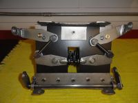
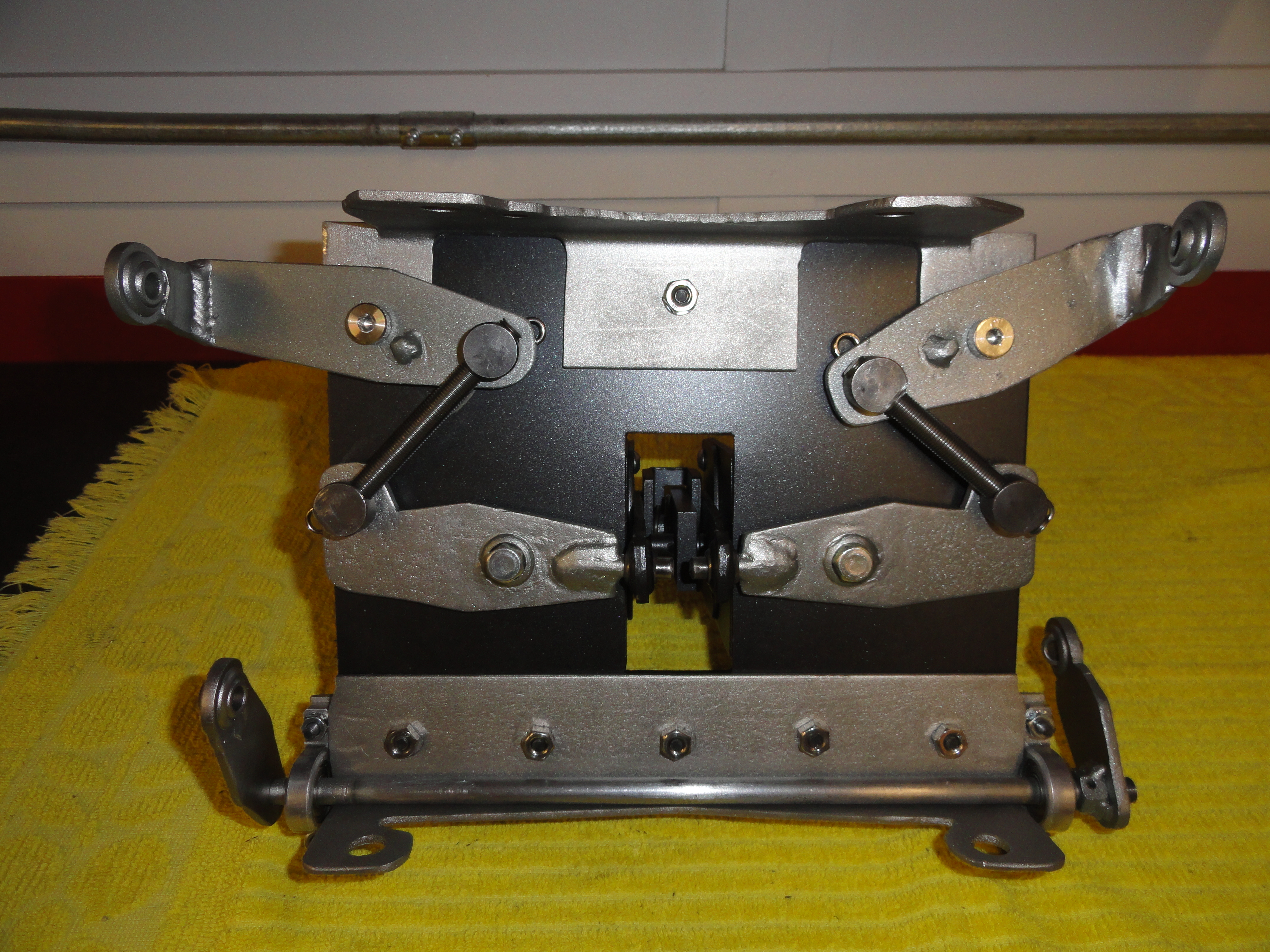
 Now you should have something that looks pretty much exactly the same as this picture. The mechanism moves freely and there is no resistance throughout its movement. Don't worry that your mechanism isn't moving through the entire top to bottom area. This is by design. For our old trucks, we don't need that much movement to get the job done. We have one more thing to do before we can start driving around with our new floor shifter. We need to make three linkages. This is what we will do with the rest of that 36" piece of all-thread!
Linkage Creation and Installation

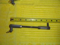
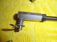 To make these linkages you will need 6 of the 3/8" long coupling nuts per parts list number 12. On one end about 3/8 of an inch down from the top of the nut, drill a 5/16" hole to accept a piece of 5/16" round stock. The round stock will go completely through the coupling nut and flush with the backside. Cut 6 pieces of 5/16" round stock that is 7/8" long. Drill a 3/16" hole about 1/8" from one end in the center of the rod for placing the cotter pin as shown. The washer and spring is re-used from the trucks current shifter linkage.
Weld the 5/16" rod by placing weld inside that end of the coupling nut. Pretty solid way to hold the rod in. Sometimes things just work out! Now, cut three pieces of 3/8"-24 all thread that is as follows: The right side bearing linkage can now be installed. With a 3/8"-24 lock nut spun onto each end of the threaded rod, spin on your linkage ends. Make linkage have an overall length of 7-7/8". Lock them down and install on the outside of your right side bearing pivot assembly. As always, rotate the bearing pivot to ensure everything moves very smoothly. This is the first time you can actually see the movement in action for your Reverse and 1st shift lever on the correct side of the transmission.
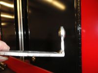
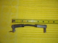 Now we tackle the harder one, the 1st/Reverse linkage. This one is harder because we have to bend it a bit. At 3 inches down one side of the 5-1/4" rod, put a bend in it. How much? I am not an engineer and I really don't know how to tell you, so try this: stand the rod up on end in front of you so the top is at 12 o'clock. Bend the bottom until the bottom is at just a little less than 5 o'clock. No kidding, just a slight bend. 5 o'clock is really a smidge too far. Try not to mess up the threads in doing this. Easier said than done. I use a series of nuts spun together on each side of where I want my bend, then put it in a vise and whack the nuts with the hammer. Put your locking nuts and linkage ends on this piece so its overall length is about 7 inches.
 The 2nd/3rd Linkage is as easy as the first one we did. No bends. Make that one an overall 6-1/4" (using the 5" rod). I added springs to mine that go around the 5/16" rod end to give the linkage more stability and less flopping around. I got the springs from Harbor Freight's Storehouse spring kit. That's also where I got the hairpin clips so I had various sizes. Add a 5/16" washer and you have the same thing they had back in the day.
Finally, once you have your linkages all adjusted and you are happy with all this, you could use some 3/8" heat shrink tubing to dress up the linkages a bit.
Installing and Adjustment
Now that the hard part is over, let's see how we did. Remove the transmission floor cover. If it's the 3 speed one, you will need to purchase the 4 speed cover or modify your old one. You can purchase cloth shifter boots that would work with the 4 speed cover, or go to a lot of trouble and make a tin solution. I am hoping for someone out there to comment with a good idea.
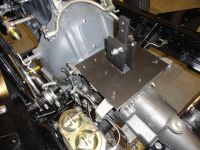
After you have the trans cover removed, remove the top two bolts that hold the transmission to the bell housing. Set the unit on top of the transmission and move it forward and install those two bolts back in, mounting the front of the shifter unit. If it's a stock 3 speed, you can install the additional mount as well. Bolt them together, then remove the top torque tube bolts and use those same bolts to mount the rear. If it's the overdrive model, remove the three intermediate bolts and reinstall them mounting the rear of the unit. That's all there is to mounting.
 To test your new shift mechanism but just in case you want to keep your column shifter for now, take the two column shift linkages loose from the transmission levers and tie them back. Install your new linkages. The 2nd/3rd (front trans lever) is really easy. Just put it on to the inside of the two levers. They should be fairly across from each other. The 1st/Rev one will be a little annoying because it's so tight there. Install the linkage with the longer end before the bend at the transmission lever, and the shorter end to the mechanism. The bend points sort of down and directly to the front. It's tight there. If you get totally frustrated and can't get the linkage which goes inside the Heim joint and to the outside of the trans lever, remove the mounting bolts and install the Heim joint side of the linkage, THEN reinstall everything. Whatever works. Once it's there, adjustments happen with it properly installed.
So now that everything is mounted, linkages connected, and everything looks right, move the shift levers in your standard H pattern as shown on earlier. Don't expect it to work right, just see where you are. Reverse and One are always engaged until you get to the center, so, are you getting the proper movement to get completely to reverse, through neutral, and completely to first? If no, make the necessary linkage adjustment. Remove the linkage from the trans lever since the other side is so hard. then change the length as needed. Look carefully at the action to make sure nothing is hitting or binding. Once you have the entire movement of the transmission lever at your command at the shift lever, put it in Neutral. Since you did all of the above, it also means your 2nd/3rd lever is in Neutral already. The big question now is, are the two shifter arms inside the tower perfectly across from each other? Chances are they aren't. So, this is where you remove either R/1 or 2/3's primary pivot clip, drop the button and make the threaded rod longer or shorter. Move the pivot by hand once you have dropped the button to see what I am talking about. This adjustment is to get those two bars to be exactly across from each other to form your H pattern. Since you are sitting to the left, you might want to make it so the H pattern is slightly angled toward you to make it feel more natural. Remember, this system should not bind, hang up, or do anything but shift very smoothly. You should feel when each movement "kerthunk's" into place. If your pivot bolts are tight, just the correct amount of slop is there.
So, I ask you, are you happy? Drop me an email at deve@speedprint.com. I want to hear any negative feedback as well. Maybe there is something constructive we can do to make it even better.
Meanwhile, here are those full size templates I promised you. Print these templates out as many times as you need to do it right. What I did when I was using paper templates was to cut the template out with scissors, then tape the template to the work and then using a center punch, hit through the paper in the center of the holes. As long as your printer is printing at 100% they will be in the right place. Be as precise as possible and don't get in a hurry! Follow the instructions here carefully. This was a real confidence builder for me, so I know if I can do it, YOU can do it!
Get the Full Size Templates Here: Full Size Shifter Templates
NOTE: If your computer's printer is like just about everyone else's, it prints at 97% by default. This is bad for our purposes, so whatever you do, go into your printers settings and make sure you find the field where it says 97% and change it to 100%.
The Shifter Handle:
As I stated previously, I had my local machine shop handle this because a metal Lathe is required and I don't have one. To help you get it right the first time, here are the dimensions:
For the Hurst mechanism: 5/8" x26-1/4" High Strength Aluminium keeps the weight down in a place where weight is the enemy. The first 3 inches are squashed so that we can put two 3/8" coarse thread bolts spaced 7/8" apart for mounting the handle. At 8 inches, we make a bend to 36 degrees.
For the Mr Gasket mechanism: 5/8" x26-1/4" High Strength Aluminium keeps the weight down in a place where weight is the enemy. The first 3 inches are squashed so that we can put two 3/8" coarse thread bolts spaced 7/8" apart for mounting the handle. At 8 inches, we make a bend to 53 degrees.
To finish off the top is female threaded to 1-1/2" to accommodate a piece of 3/8-24 All Thread. Cut this about 2-1/4" long and use Loc-Tite, then you can spin your shifter knob on without problems. I got a great looking black with inlaid white pattern knob from a company called Twisted Shiftrz. My favorite knob for this truck is the one available on Stovebolt.com.
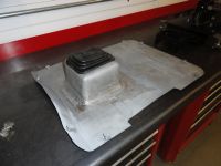
 It would really be nice to get some feedback on this one. I know it works perfectly, but the ONE thing I would have liked to figure out better is the boot that covers the tower part of the mechanism. You can purchase them on Ebay Motors for generic use. This is what I came up with for myself. But it's way to involving to do for anyone else with my metalworking toolset. To explain further, as an Avionics Technician in the US Air Force back in the day, I really liked the Dzus Fastener and decided to make my transmission cover accordingly. So there are 1/4 turn fasteners where the sheet metal screws used to go. Then, I put a dual master cylinder in so made a rectangular opening in the floor to accommodate. Lots happening in a short space with this cover, so that's why it looks so different in the pictures.
By the way, if you decide to take a crack at making this shifter mechanism yourself, there are LOTS more pictures available to help you along. If you need someone to make one for you, let me know and I will find someone!
More Pictures available at The Site Archive Page!
This article was first published at DevesTechNet.com (c)2015 All Rights Reserved
Note before we get started...
The idea is for a group of interested restorers to create something I call 'Solution Criteria'. In other words, what do we want this project to look like EXACTLY. In this case we used the following for Solution Criteria:
3 speed floor shifters are notoriously a bad idea due to how the transmissions linkages are on the left side. Because of the location of the shift levers, most hackers just hack a hole way back near the seat pedestal and on the left side, then make a shift lever that 'works'. So here is #1 solution criteria:
a) The shifter must come through the floor in the exact same spot as the STOCK 4 speed transmission did when the truck was new.
We don't want to source out universal shifter levers for our transmission, we want to use the stock 3 speed levers in the stock configuration. Why is this so important? Because if you decide you don't like your floor shifter mechanism, you shouldn't be penalized for it. You should be able to re-attach your column shifter in a matter of seconds without worry. So here is #2 solution criteria:
b) The stock transmissions shift levers must remain in the stock orientation without any modifications.
We do not want to use a system where off-board pivots are used to accomplish this. We want the shifter to be mounted directly on the transmission and we want to feel the vibrations of the drivetrain just like you can with a stock 4 speed. So here is #3 solution criteria:
c) The solution must not have any chassis or off-board mounting parts.
4) After all of the above, we absolutely do not want any slop introduced by the solution that would make the shifter feel sloppier than a stock 4 speed. Truth be told, this isn't too hard because the stock 4 speed had LOTS of slop in it, but this solution is much tighter and more responsive. So here is #4 solution criteria:
d) The solution must be as tight and responsive as the stock 4 speed shifter.
So as you can see, this effort is different from anything you have ever seen before. The criteria is first and foremost. We do not 'settle' for anything less than what we originally set out to do. It's either everything we want, or it's not at all. This philosophy will be front and center at devestechnet.com. We are not in this to make money, just solve problems in a very productive way. Of course if someone wants one of these shifters and can't make it themselves due to shop or experience limitations, depending on availability of experienced shop experts, we can arrange to put together the resources to make one for you at no more than standard shop rates. This isn't about profits, it's about giving back to a very worthwhile community. Whatever you do, if you got this far, let us know what you think!
 Back in the day, when you went to purchase your new 1947-55 Chevy Pick-up you had two options; a 4-speed transmission with the shifter on the floor, or a 3-speed transmission with the shifter on the steering column. The three speed column shift option had its advantages. It allowed for more comfort for the middle occupant. Also, it was a popular mechanical solution and sold very well.
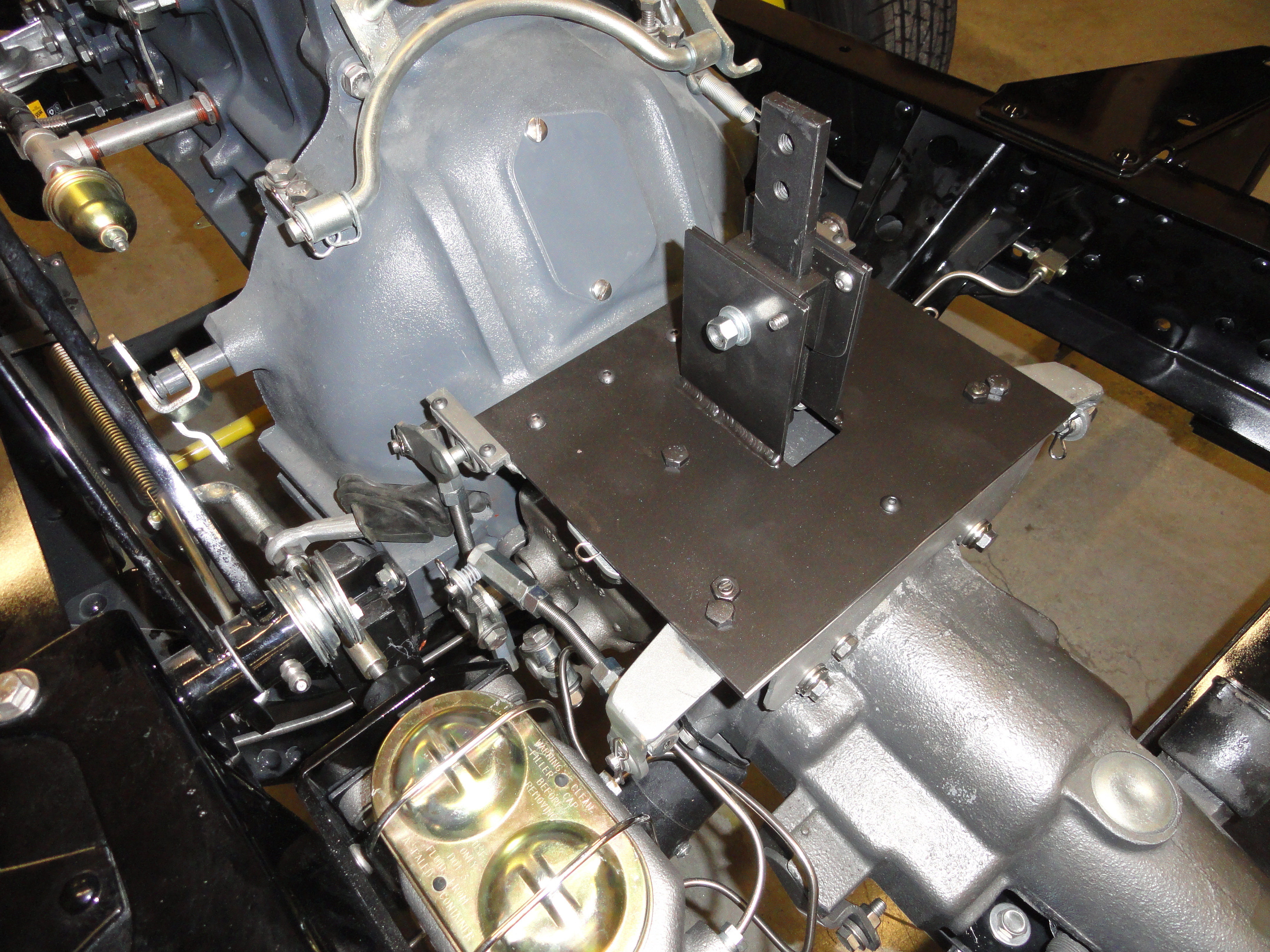 But if you are like me, and reminisce about the old truck with the stomp starter and the shifter on the floor... driving down the road with one hand on the wheel, the other on the shifter.. feeling the drive-train, its vibrations, etc. all directly, then you prefer the floor shift. Not to mention, some of us gear-jammers couldn't keep them adjusted!
But alas, we have a 3 speed or 3 speed with the Borg R10 Overdrive and we still want the shifter on the floor. NO, we do not wish to put the shifter in some unorthodox location to the left and near the seat pedestal. NO we do not wish to hack up the floor and put in some universal shift kit. WE want our shifter to come through the floor in EXACTLY the same location the 4 speed of the same vintage did. WE want to use the stock transmission levers in their stock positions. WE want to purchase a 4 speed transmission cover from our vendors and expect it to work perfectly. We also do not want any off-board pivots or anything to dampen the true vibrations of the drive train. Many of you reading this are laughing because for 60 years, nobody has been able to make this happen. After-all, there is less than 1 inch of space from the top of a 3 speed transmission to the bottom of the cab floor. I hate it when people say.. 'you can't do that', don't you?
 After many hours of research, making several prototypes and lots of head scratching, here is the solution that does everything we want. I hope you feel the time to do this was worth it. I feel the same way James Smithson (of Smithsonian Institution fame) did when he said "I do this for the increase and diffusion of knowledge among men." So no patent pending here. It's all here in this document for you to make yourself if you so choose. Have as much fun as I did! Whatever you do, drop me an email telling me how you like it, what improvements we can make, etc.
The "engine" for this project is a universal shift mechanism. Basically the top part or head of the unit. It's a bit expensive to create your own shifter mechanism and I didn't feel like re-inventing the wheel, so go get yourself a Hurst shifter kit [part number HUU-5010016] for about $225.00 OR a Mr Gasket shifter kit [part number 7667A] for about $50. They both work equally as well and require the same modifications. The only reason I mentioned the Hurst offering is because I purchased that one first.
The thing that makes this all possible is the Heim joints. The Heim joint is a ball and housing that rotates bi-laterally as shown below. We don't care about the threaded part, so the female ones work just a little better than the male ones because the cutting area is more emphasized.. Then, you may find uses for the threaded part for other projects!So now I will try to explain what is happening here. We have virtually NO room to work with, about 3/4 inches at the front of the transmission and about 1-1/8" near the back of the area in question. The driver's side of this mechanism is very straightforward. The linkages end up meeting exactly where we want them to. But the other side is another issue altogether. We need to move the action from the wrong side of the transmission to the left side. To do this, we will use a 3/8" shaft (12-1/4" long) with two small bearing assemblies with housings. This also then puts the linkage in just the place we want it. Easy peasy right?
In case you are more of a genius type and are asking yourself why two pivots on each side instead of a much easier single pivot point, it's because doing that reverses the shift pattern. Not only do I want all of the features I outlined earlier, but I also want the shift pattern to be standard. Here is what your transmission's levers are doing:So, a single pivot would make it shift backwards. Another consideration that is quite important to the success of this project is that the truck's shift levers need to be standard, and in the stock location. If you have changed your shift levers from stock, change them back! Some of the readers of this document will want to shift a Borg R10 Overdrive unit. No difference from the 3 speed except that the Borg R10 was not original to the truck, and the transmissions shift levers may not be in the place they should be. The RIGHT way to resolve that is to get a side plate from an original 47-55 3 speed transmission and replace the shift lever assembly. The other reason for doing that is if you ever want to put a dual MC on your truck, your incorrect lever shafts will interfere. Ask me how I know! Another way of course is to get two universal shift levers and just point them in the right position. Here is the correct placement. It's from the shop manual.So now that you have your shift levers correct on the transmission, and your 4 speed transmission cover, you are ready to tackle this pretty involved but very satisfying project. Understand that I did all this with very rudimentary tools as far as metal working tools go. You will want to make friends with your local welding/machine shop because there are things they can do for you to cut down on the approx. 160 hours of time it takes (equiv. to one full week) of labor if you do it all yourself. We aren't whistling dixie here folks.. it's quite a project. But imagine how you will feel once it's done and works exactly as advertised. Nobody, and I mean virtually nobody has this setup on their truck, so the satisfaction that you will feel pulling this off will make it all well worth it!
Tools List:
As I said earlier, I don't have an unlimited tool budget. I use what I have. So if you have better, consider yourself fortunate. If anyone has a free Laser system they would like to donate to a good cause, I am your man!
- 4" Makita Grinder - Most of the work was with thin cutoff wheels, some was with 120 grit flapdiscs, and it wouldn't hurt to have a regular grinding wheel. I suppose I went through about 8-10 thin cutoff discs.
- DeWalt PortaBand bandsaw with the Swag Offroad Table - If you do any metal cutting on things like this, it really pays to get one. Truth be told, if you don't have one and are too cheap to get one, the Makita and some talent will work, but it won't make things any easier.
- Drill Press capable of chucking a 1" metal cutting bit - Mine is really an embarrassing foreign knockoff used in my woodshop, but it's all I have. It works, so nothing elaborate is necessary.
- Dremel 4000 with carbide grinder bits - If you look carefully at what we are fixing to do here, there is some pretty involved sculpting required that a Makita grinder just isn't capable of. An entire set of 1/8" shank carbide rasps at Amazon are less than $20. If you insist on a 3 inch air grinder with carbide rasps, you can use that too. I feel you will be happier with your work the closer in you can get, so the Dremel really works best.
- A good punch to mark your holes, tape measure, marking pens for marking steel (I use Sharpies), a good all around drill bit set, level, straight edge, you know the drill!
There are times in the drawings I use the next size higher drill bit. Instead of 5/16" I might specify 21/64". Other times I may not. This is by design. Please use the specified bits so that you don't end up with slop. Slop is a shifters equivalent to the devil. We are doing everything I know how to prevent slop and give you a very clean shifter.
Shifter Fact! Most people do not realize that when you disconnect your shifter from the transmission, it just dies. Just like a robot that gets shut off. No detents, no clarity in its purpose, just slop, slop and more slop. It's the transmission that FULLY provides you with a clear Neutral, and gear system. The shifter does nothing except organize your shifting into a pattern. My first attempt at this design, I had installed special detents to further emphasize Neutral so there was a clean, concise difference. It failed because it's not needed, nor desired.
Parts List:
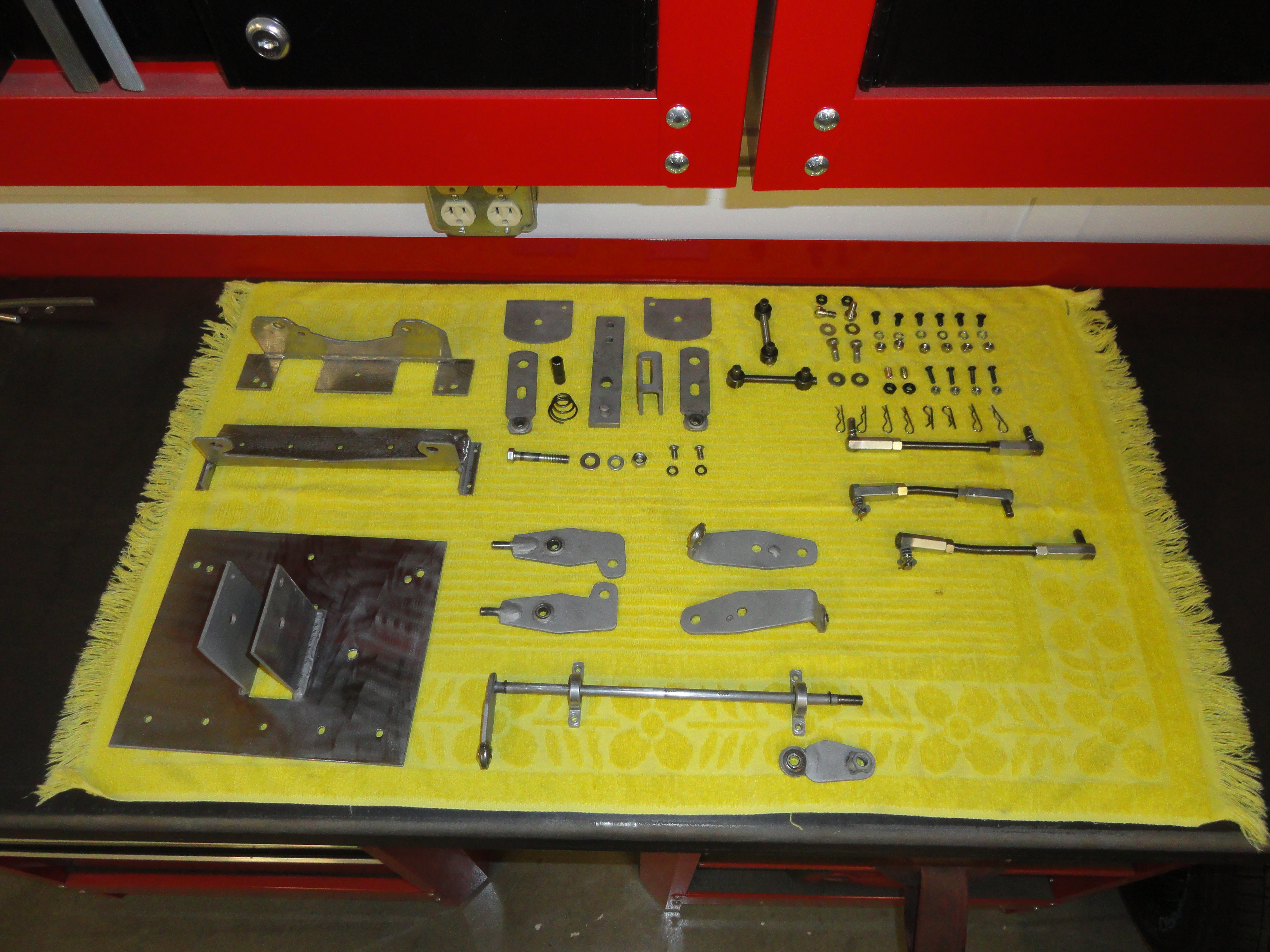 Metal is expensive, but what I do for my projects is to get used, repurposed, or small cutoff pieces from a local welding shop scrap pile. I will list the metal and sizes you need here. You cannot get a single piece for the frame of this project for mechanical reasons, so please follow the list carefully. There will be a reason for everything.
- 36" of 1/8" by 2 inch Angle Iron. You will need about 16 inches less if it's an overdrive trans.
- One Piece of 10" x 8-3/8" 10 gauge plate for the top. 10 gauge is very much the same as 1/8" so either is fine.
- Two Pieces of 10 gauge 3 inches by 4 inches for the tower.
- One 36" stick of 3/8" round stock. It must be exactly 3/8" or maybe a smidge less because the precision bearings you will use with it will not work with slightly thicker. This was a problem and I had to go back to my supplier a few times looking for the right size. In other words, 3/8" is not necessarily 3/8"!
- One 24" stick of 5/16" round stock. This also goes into precision Heim joints but didn't run into problems with it.
- One 36" stick of 3/8"-24 All Thread. This is a stick of purely threaded rod with the 24 fine thread pitch required for the project.
- 4 each Hurst Shifter Buttons. I wasn't happy with the $40 cost for 4 of these, but they are necessary. In case the link dies, they are Hurst Part No. 1193783. I get them at Hurst Shifters Online
- 5/32" plate stock for cutting out your pivots. 5/32" is just a little heavier than 10 gauge and works best with the shoulder bolts required for securing. Got to control the slop! Get at least a 10 inch by 20 inch piece for the misc parts we will need to cut out.
- 8 each 5/16" Heim Joints. I haven't been able to find them without threads on the end. All we care about is the joint itself, so we will cut off the threaded part. I find the female joints the easiest to cut off with the added benefit of having a long nut that could be used for something else later. Here is the link: McMaster-Carr Online
- 2 each 3/8" locking shoulder bolts. The shoulder is 3/8", 1/4" long shoulder, and 5/16"-18 threads. Here is the link: McMaster-Carr Online
- 2 each Heim Joint Washers. These are only needed at two places in the assembly. They help add a little more radius and raise the pivots to the correct height. Here is the link: McMaster-Carr Online
- 6 each 3/8"-24 Coupling Nuts. These are for the linkage ends. Here is the link: McMaster-Carr Online
- 2 each 3/8" Bearings w/Housing. These are transferring the shifter energy to the correct side. Here is the link: McMaster-Carr Online
- 4 each #10 find thread 1 inch long bolts and lock nuts to secure the bearings above. Here are the links: Screws: McMaster-Carr Online and Lock Nuts: McMaster-Carr Online
- 2 each 5/16"-18 hex head cap screws. It is very important these two screws have 1/2 inch of unthreaded shank on them. I find the 1-1/2 inch ones have the right amount from my local hardware store. I don't source these from McMaster because the shank is so important, I need to see them. This enables the heim joints to spin properly without slop. You will be cutting them down to size once everything is assembled.
- 4 each 5/16"-18 Thin Hex Nuts. These are to fasten the shoulder bolts and above cap screws to the upper plate. Here is the link: McMaster-Carr Online
- A Mr. Gasket 3 speed Manual Shifter Kit part number 7667A. I just get them off EBay for about $50. The only part of it you will use is the mechanism itself.
- Shifter mast and knob. You can get a 5/8" high tensile aluminum rod and make it yourself but you would need to weld threads on the end for the knob. I have them specially machined and bent. It's cheaper for female threading, so I just add some 3/8"-24 all-thread to the end to accept the knob. More info in Assembly Instructions next.
Since we are making parts from scratch, this may seem daunting, but it's not really that hard if you have the Tools in the list. Let's start with the 10 inch wide by 8-3/8" long, 10 gauge plate. There are full size templates at the end of this instruction.
The hardest part of this plate is cutting out the rectangular hole. The hole is 3-1/4" by 1-1/2". It is placed in the very center of the 10 inch dimension, so measure and put a mark at 5 inches, then go 3/4" to each side. For the 3-1/4 inch dimension, measure from the top, 2 inches down, then start the 3-1/4" per the template at the back of this manual. This should be as precise as possible. I used my 4 inch Makita grinder with thin cutoff discs, then finished the corners with my Dremel tool with 1-1/2" thin cutoff discs.The two 5/16" holes adjacent to the cutout must be exactly centered on the 3-1/4" opening. This serves as the primary center pivot. Drill the holes 4-5/8" from the bottom, and 2-5/8" from each side.
The other two 5/16" holes are 3/4" from the sides and 1-1/2" from the bottom of the plate. Try to be as precise as possible.
The next step is to make the front piece. This is simply made with 1/8" x 10" piece of angle iron. There will be some trial and error here. This is why I provided the actual size templates at the back of this document. It will not be perfect, but it will get you there. The reason for it not being exact is because the cast housing of the transmissions are all slightly different but mostly due to the precision of your work in sculpting this piece. The front and rear pieces are the hardest part of this.
Be sure to sculpt the correct side. Concentrate on the straight lines first. This is where the porta-band with table really comes into play. Once you have it all marked with your sharpie, just do whatever gets you there! Marking the back side of the angle iron is the most difficult. Be sure to do your diligence in measuring and marking before you make your cuts. I suggest drilling the two 1/2" holes first. Make sure you use a good punch and measure exactly 8-1/4" between the two holes and 7/8" from the edge to the center of the hole. It's important to get these two holes exact and balanced so that the plate mounts perfectly straight. The holes are also 1/2" from the bottom.
For the rear piece, we use another piece of 1/8" x 2" x 10" angle iron this time with a twist. It would be really nice if we could get 2 x 2-5/8" angle iron, but since we can't, you will have to add a 3/4" strip to one end. Since we are using 10 gauge for the top plate, we can also use that for this strip. Be sure to bevel the ends before welding to add strength and ensure a very nice flat weld. The left and right 7/16" holes are NOT exactly across from each other, so be sure to measure carefully.NOTE: This added strip, the holes and some of the contour can be eliminated if you are doing this for a standard 3 speed stock transmission. This piece must be precise for R10 Overdrive units only. Read this document in its entirety before starting so you are familiar with the why.I just welded the strip all the way across so there were no worries about getting it placed right. Both diagrams are outside views. (the bend is nearest you).
Anytime you are doing custom work of this sort, patience is a virtue. Just like with the front piece, lots of sculpting here. Be very careful to measure properly when to transferring the template to the back of the work for cutting with the bandsaw table. Cutting the holes first will make it easier and more flat in the end.
Ok, so you have the main parts made and now we need to assemble them. Are you familiar with a technique called spot welding? In case you are not, it's just drilling about 7/16" holes every so often in the angle iron only, then weld through the hole to fix the two pieces together. So, get to it! Drill about 4 holes at intervals that make sense and do not interfere with the workings. Take a look at the pictures on page one and do your thing! But, education is always first, so, before you just haul off and weld stuff, bolt the front piece to the transmission/bell housing connection and check that your bolt holes, sculpting, ect. are dead on. If they are not, don't feel bad, just use your Dremel and change the configuration a bit to match your system.
Once you have the front bolted on and it's all tight, bolt on the back and see how it looks. It should be centered on the transmission and front piece and it's a simple matter of placing the top plate on and it should all be perfectly square. But even better than getting it square, put a level on it (front to back) and it should show perfectly level from front to back. This is needed so we have the room we need to add the mechanical parts. Don't get too bent out of shape if it's a little off. It won't matter. If you are an 8th off, no worries. If it bothers you, fix it! The template was designed to make the entire platform perfectly level from front to back, and left to right.
Important. Once you have it bolted to the transmission, take a few vise grip clamps and clamp it down hard for welding. Then it's all a matter of a nice clean installation.
NOTE: I am describing the rear piece as something that bolts to the transmission. Of course you see the fallacy of this if you do not have an overdrive. But, it is all still very valid because the sculpting you did will sit on that "spine" that is front to back on the stock 3 speed and be just as level. So, if you have the stock 3 speed, just bolt the rear piece on to the very edge of the top plate as you expect it to, and move on. There is a nice stock 3 speed bracket in this document but we are not there yet.
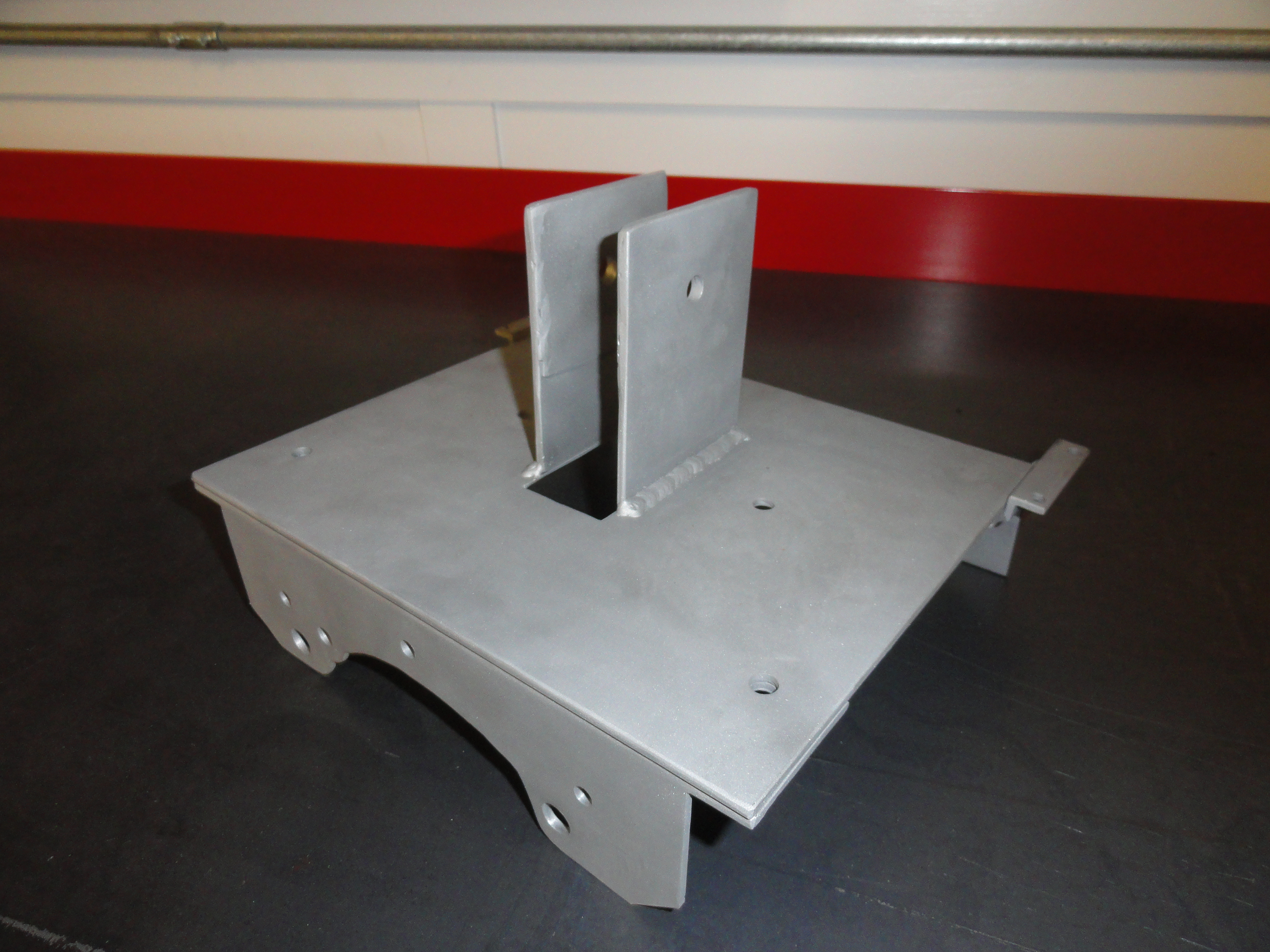 So, now we have a tower and a Hurst or Mr Gasket shift mechanism to contend with. It was just easier and more economical to use what is already there. No sense in re-inventing the wheel. I suggest going with Mr Gasket since it's cheaper by about $200. They are similar, but they are NOT the same. Where you pay even more for the Hurst is when you need to bend the shifter mast differently. The Mr Gasket bend is less radical. This is due to the offset levers they use in the mechanism. Here is the difference, or check out the templates in the back.
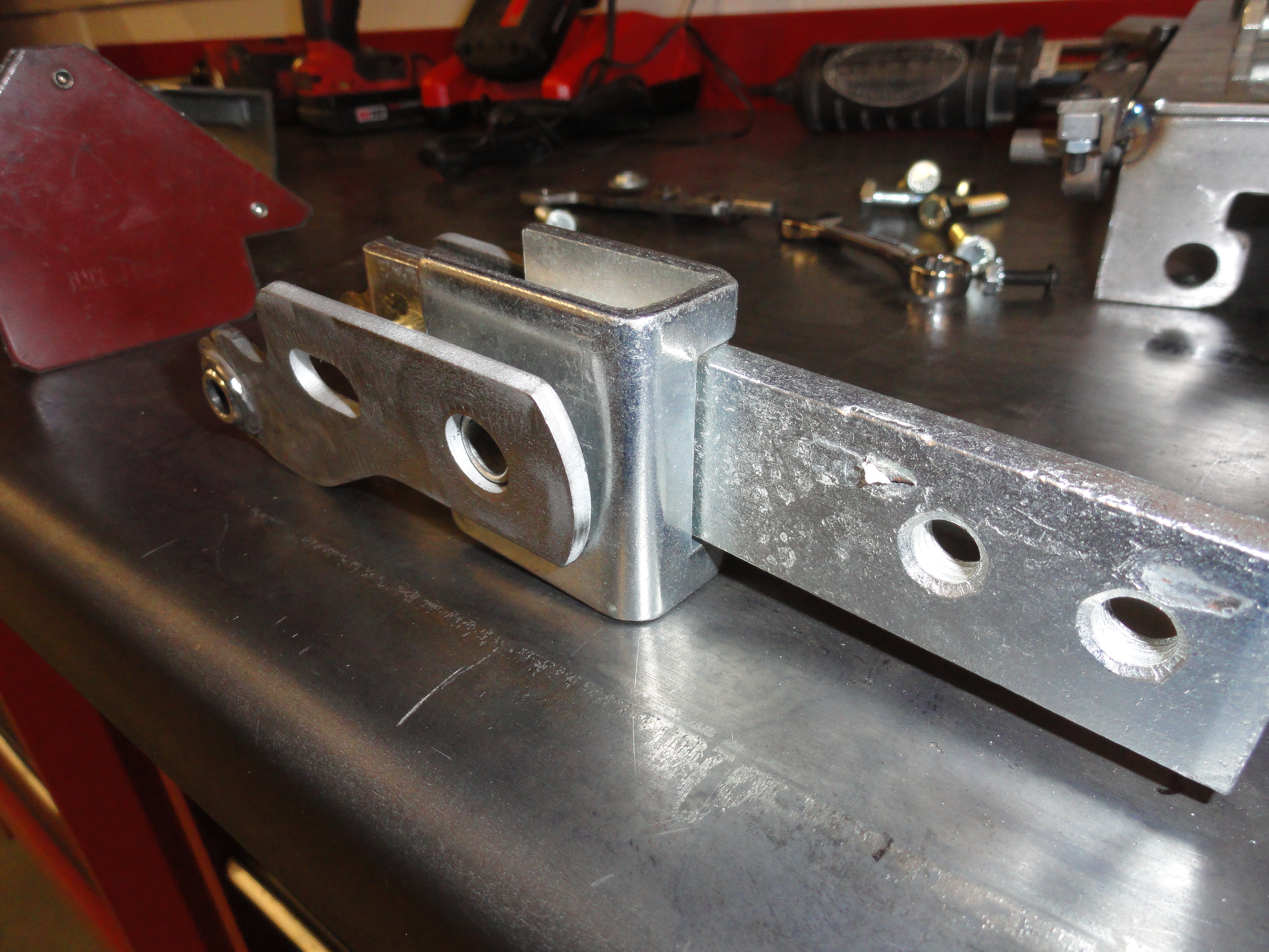
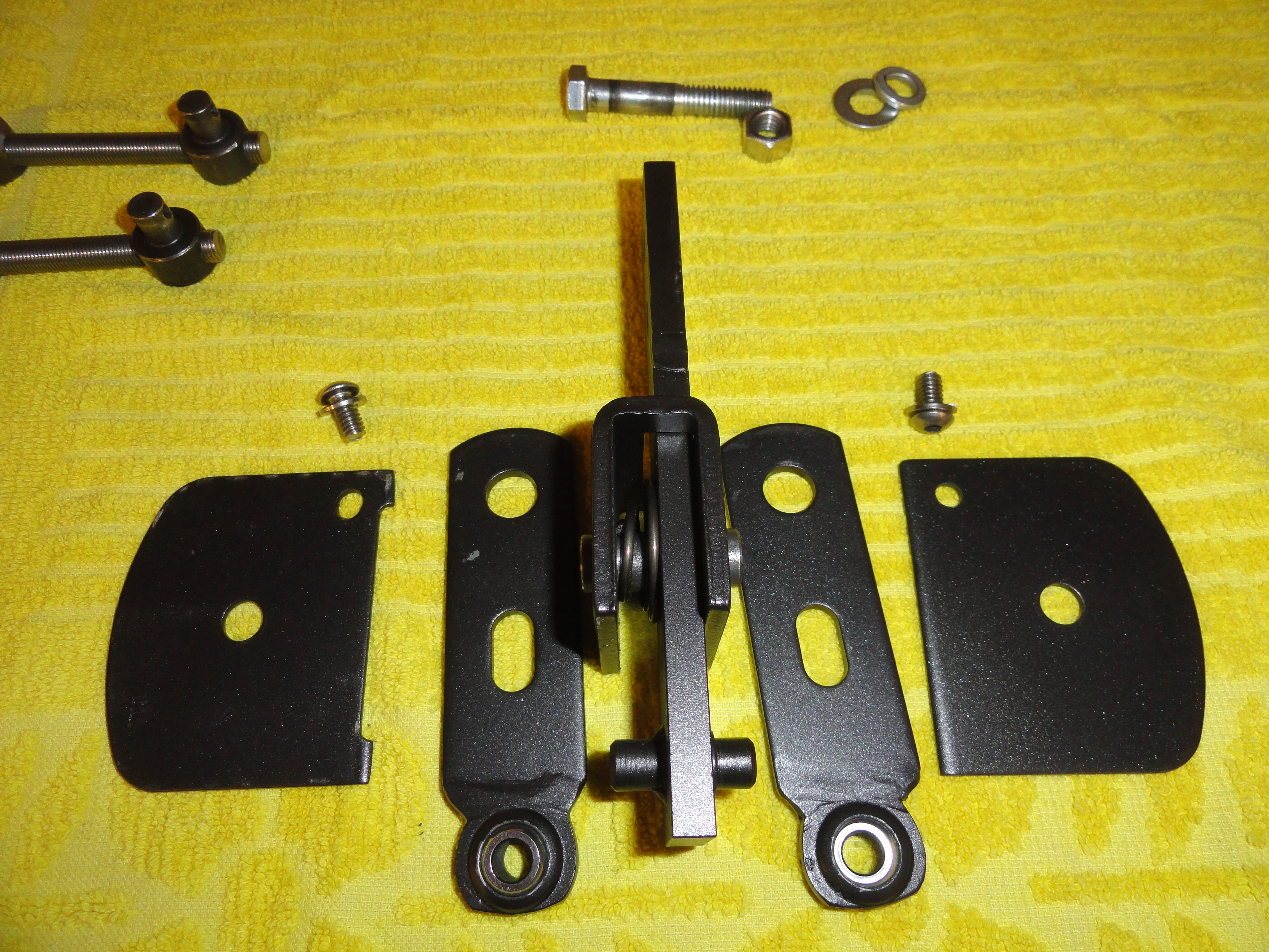 (Left to right: Mr Gasket, Hurst) Since this is a solid design, we can accommodate both with minor adjustments. So let's make the tower bracket to fill that 3-1/4" by 1-1/2" hole you labored over in the top plate. Using 10 gauge steel. Cut out two pieces that are 3 inches by 4 inches. The hardest part of this procedure is trying to get the center hole at the proper height for the lower mechanism to meet up properly. There are two issues we are concerned with here. One is proper hole height, the other and opposite issue is the Heim joint lever length that corresponds to the hole. So let's take the hole question out and just place it at exactly 2-3/4" from the bottom.
I am making a point of this for a reason. Drill this 3/8" hole in the very center of the 3 inch (1-1/2") dimension and 2-3/4" from the bottom. Make two of these:
Note: If you have the mechanism in front of you, the center pivot bolt will go through the holes in your two plates. Best to drill the holes together so they are exactly across from each other.Take the mechanism, and install it between your two plates. Of course the center shifter bar goes UP and the pivoting assembly goes down. You will be removing this assembly several times, so don't expect anything permanent yet. With the mechanism installed and both plates straight with each other, set this assembly on your top plate. It is not designed to go IN the hole. It's designed to set exactly over the hole. Use those special welding magnets to hold it perfectly straight. Check and recheck this before welding. Now, important, the front of the assembly must be exactly 2-1/8" from the front of the mounting assembly. This puts the mechanism in about the center of the hole, maybe a little forward. This puts the shifter right in the middle of the 4 speed transmission cover. Once you understand where it goes.. hopefully I described it so it makes sense, weld the mechanism to the top plate. Weld on the outside and top side only!
Now you have two plates welded to the top piece that hold the shifter mechanism. Sadly, the two levers will need to be removed and modified so get used to lots of removing and reinstalling these parts. There is no need to mess with the spring, center pivot pin, or main shifter bar. Go ahead and remove the two lever bars from the mechanism. You have the pictures to the left to help you with putting them back together. Now we will do one of the more intense modifications. The two levers will need Heim joints welded in to replace the two holes at the bottom. Here's the thing. Remember the big deal I made about the center hole (above)? Well, this is critical that you get those Heim joints to the proper length to go down below the plate, but not so far as to hit the top of the transmission. We are talking about Nths of an inch here. It must be very precise.
For me, the hardest part of this project after sculpting the front and back is getting these Heim joints welded in properly. To prepare for doing this, let's get all the Heim joints prepared for the project. There are 8 of them and they all need a little preparation. We want to remove the female thread portion and be left with exactly 1 inch of just the center part. I did this with my Porta-band with table and it was relatively easy. Try not to overheat these pieces. It is possible to warp the mounting for the center ball causing them to hang up. Use a Makita grinder with a 120 grit flap disk to smooth the work and eliminate sharp edges. The Heim joints with the female threads have a distinct crease at the one inch mark so thats why it's just easier to get the female ones. Do all 8 while you are at it.
This is the Hurst shifter forks dimensions when you are done. In the case of the shifter forks, you will need to further grind off the "bottom" after they are in successfully. Notice you have two holes on both Mr Gasket and Hurst models at the bottom. We won't use the bottom one at all, and we are replacing the top one with the Heim as shown.Make two of these exactly the same. The Heim joints are centered on the shifter forks. In other words, looking at it from the side, it should be the same on both sides.
This is the Mr Gasket shifter forks. Although they look different due to the offset nature of them, the dimensions are the exact same. The advantage of going with Mr Gasket is that the offset causes the shifters mast to favor the space inside your truck a little better. But it's not a huge deal since bending the shifter mast a bit more is an option.NOTE: Don't forget about the full size templates!
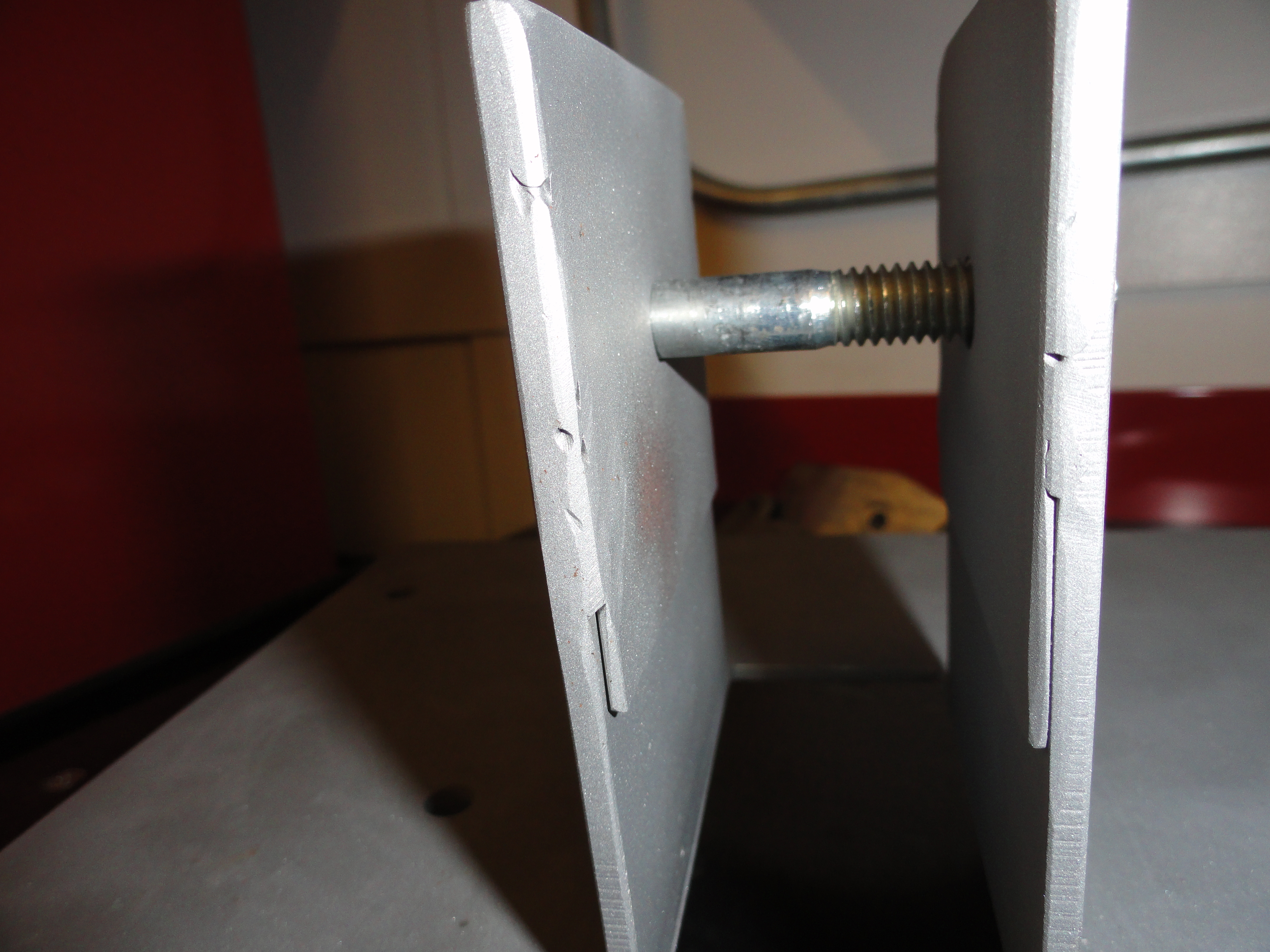 The only difference at this point is the shape. The 3-5/16" between the holes is the very same. This shape is a plus because it moves the shifter mast more forward. With the Mr Gasket shift mechanism, we need to make a few 20 gauge plates that came with the Hurst shifter mechanism but didn't come with the Mr Gasket one. Cut two pieces of 20 gauge 3" by 2-1/2". We place these on the outside of the Mr Gasket mechanism, but inside our 3" by 4" tower. Place them at the top inside of the bare tower without the mechanism installed. Mark the tower holes and drill a 3/8" hole for the mechanism in both of them. As shown.
The Hurst shifter comes with this, but the Mr Gasket one is really more suited for our purposes, so it's a small price to pay just to add these two plates. Once you have the plates made and tested to fit, spot weld them in so you never have to worry about them again. The reason we are doing this is to allow the shifter arms to move more smoothly. If you are REALLY lazy, you can fish in some washers in between the mechanism and the tower hole that will do the same thing. I find it a hassle since you WILL be removing the mechanism more than once.
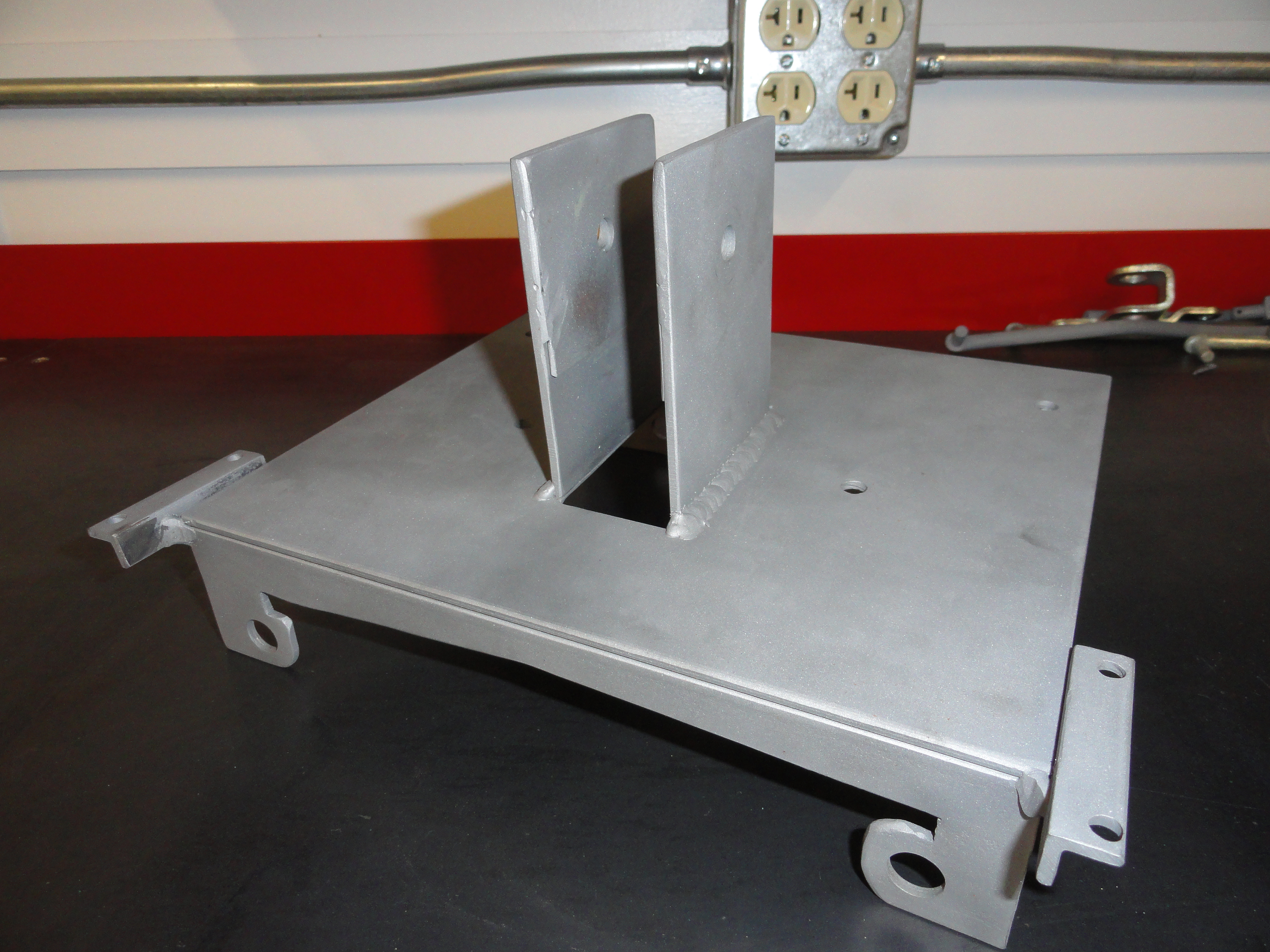


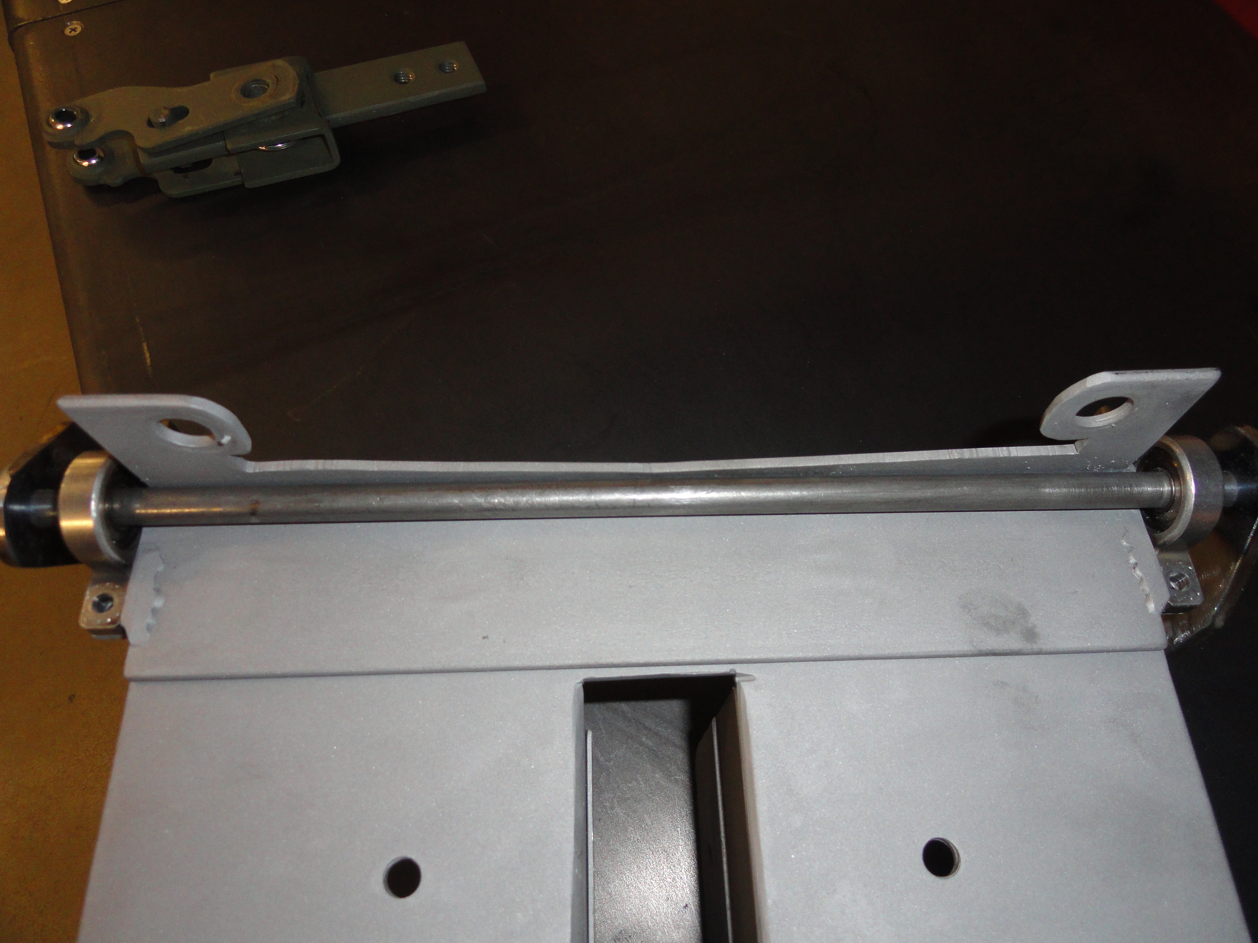
The last thing we need to do to get the framework completed is to put two 1/2" angle iron pieces that are 2-1/4 inches long near the front to accommodate the two bearing housings. The best way I have found to do this is to make the 3/8" shaft and assemble the bearings first. The 3/8" shaft rides inside the front corner of the frame. In order to weld the two angle pieces on the frame, we have to make sure the shaft very freely rotates in place. Cut a piece of 3/8" round stock that fits the bearings and bearing housing you purchased from McMaster-Carr. Test fit the bearings because it has been my experience that some so-called 3/8" round stock is too thick. The length is 12-1/4". We will need to make two thin slots for e-clip keepers that make sure the shaft doesn't try to wander once its all together. I got this e-clip storehouse collection from Harbor Freight and used the 5/16" ones. So how I made the groove for the e-clip was to carefully rotate the rod in the prescribed locations against my porta-band saw. You can do a really nice job of it once you get the hang of it. Might want to do some practice runs before trying to do 2 of them on this 12-1/4 inch rod. Cut one slot 3/4" from each end. Go ahead install the bearings inside that 3/4" and then install the e-clips.
Look carefully at the pictures to see how to weld the 2 pieces of 1/2" angle iron to the assembly. A good idea is to mark the holes from the bearing housing onto the 1/2" angle iron and drill the two holes, then grind away the shaft area (center) so the shaft moves freely when installed. Dry fit the assembly to make sure it will rotate VERY freely. What I do is wrap painters tape around the shaft about 2 inches from each end. Wrap about 6 times. The idea is to get some amount of stand off so the shaft moves freely.
Once you have both the angle iron drilled and ground to allow for free shaft movement, and the shaft mounted to the two angle iron pieces, push the shaft as far inside the front top corner as possible (the tape will be removed giving you clearance), align the two angled pieces for welding. Make sure the angle iron is perfectly parallel to the top of the frame assembly. Weld on the bottom side and on the ends so it looks nice and is sturdy as well. Remove the tape and your shaft should do two things. It should rotate very freely and it should not be removable (the e-clips are holding).
NOTE: Now is a good time to think about cleaning and painting the housing assembly before we start installing the mechanicals. A decent etching primer and a decent spray can of your choice will do. Just don't embarrass everyone with a weird color!
 Now to get to the mechanicals. By now you have an assembly that looks something like this:
Congrats because that wasn't easy! It's all downhill from here!
Let's begin with the primary pivot. This is the hardest one to make and does most of the work. The reason for a primary and secondary pivot is the shift pattern. If you try and cut to the chase and use just one pivot you will be as disappointed as me when I made that mistake in learning all this! You really want this shift pattern to be standard. So this is what the primary pivots look like. There are two of them, one on each side. The metal work is identical, however the 5/16" round stock we use will need to be opposite each other. It will make sense here soon...
Primary Pivots
If you followed the instructions, you have 6 more Heim joints each about 1 inches round. It's important for these pivots that we use a little thicker stock to cut them out of. I chose 5/32" mild steel plate. It's just a little thicker than the 10 gauge we used for the frame yet thin enough to actually fit between the top of the transmission and the top plate. The pivots are cut into a sort of dog leg design so that later, when you are making final adjustments we can get to the clip we need to pull for adjusting the threaded rod. Here is what they look like. Don't forget to use the full size template to cut them out.Right is a picture of the side view. There are two of these in this assembly and they must be opposite each other. What makes them different is the 5/16" rod placement. This is critical to proper movement.
 Cut out your pivots using the template. Cut two of them that look identical. From left to right, the dimension is 4-1/4". The exact dimension between the two holes is about 2-3/8". More importantly, the edge of the rod end to the hole must be 1-1/2". Mark the center of your hole where the Heim joint goes. Use a center punch to mark it, then with a 1 inch drill bit and a good vise or something to hold it really really good, put BOTH of the pieces in together and drill them both at the same time. Be sure it's very tight in the vise because a 1 inch hole is pretty large and hard to get precise. Once you have the 1 inch holes drilled, place the Heim joints in the hole. Tweak them by grinding until they fit properly. The two pivots you are making are the same as far as how to fit the Heim joints. They should be centered exactly so that they protrude equally from each side.
Now before welding the Heim joint into place, drill the 25/64" hole (slightly larger than 3/8") for the adjustment rod. Do this together the same as you did for the 1 inch hole. This ensures you have a nice equal set of pivots.
Weld the Heim joints in place with the proper heat for a good weld, but keep things cool and weld slowly so you don't warp the bearing housing of the joint.
NOTE: Any time you turn the ball bearing in the heim joint and it doesn't move perfectly freely, it's because you slightly warped the bearing housing. To fix this problem, very carefully lay the pivot over a vise with the jaws open about 1/2" so the ball and housing are not touching the vise jaws. Wrap the ball with a hammer lightly to bend the housing back into shape. Flip it over if necessary and repeat. Do this just long enough until it rotates freely but is still very tight in the housing.
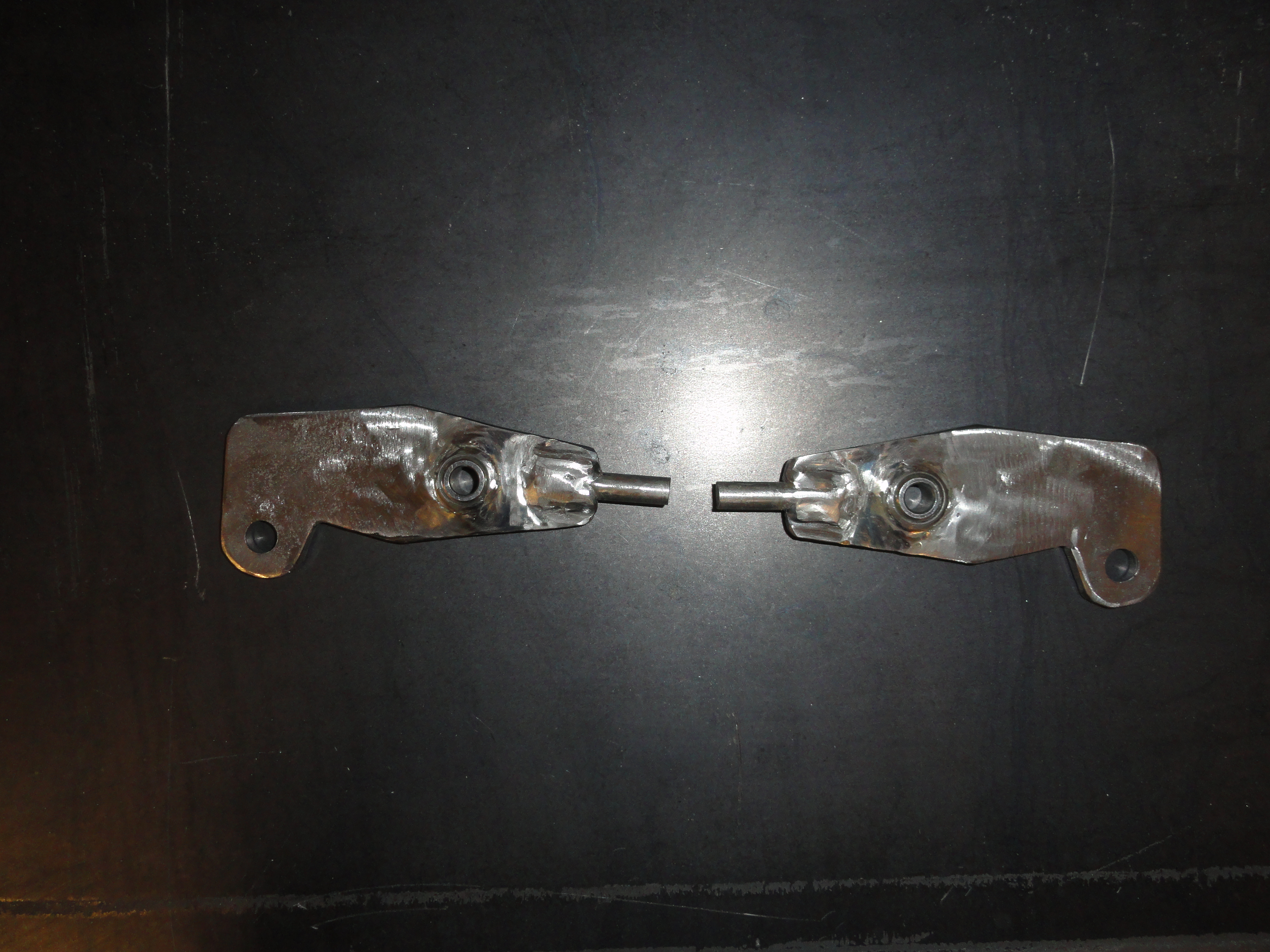 You are almost there. Let's address the ends that contain the 5/16" rod. Cut two pieces of 5/16" solid round that are 1-1/4" long. On the pivot, measure the end with the rod and CENTER the rod on that dimension. With your trusty sharpie, mark the rod location 1/2" into the pivot so that the OTHER 3/4 inches is outside the pivot footprint and centered on that end. With a makita and cutoff wheel, or equivalent, cut enough meat out of the pivot end so that the 5/16" rod completely rests ON the table on one side, and sticks up on the other as in the last picture on the previous page. A good 3/4 inches is very necessary sticking out. Do this on both pivots. Set them side by side but OPPOSITE as shown.
They must be opposing each other and have the rod protruding upward on the proper side. The protruding rod must be 3/4" and be cleanly welded so that the entire 3/4" can be used. Now that you are ready to weld, clamp the rod down to the table as well as the pivot so it's positioned correctly and go for it!
Secondary Pivots
So that was easy right? I had lots of trouble with this part on the proper angles but now that I have it down, there is an easy way to do this.. USE THE TEMPLATE!
The left and right ones are slightly different. The profile of these pivots are exactly the same on the end with the hole, through the middle. Just the last angle is different. Once you have the shapes all cut out using 5/32" plate stock, and the two downward facing pieces which are identical cut out, you can begin the welding process. But first drill the holes in the secondary pivots. The outside hole is 25/64" (slightly larger than 3/8"). The inside hole is 3/8". Follow the template instructions carefully. Next, weld the small piece that will hold the Heim joint on top of the long pieces following the angle that you cut in them.This is the part of the pivot that points downward. It works the same on both sides. Weld this piece along the edge of each pivot following the angle. Weld this piece on top of the other piece. (see Note) If you want, you can weld the Heim joint on first, but I found it easier and cleaner to weld the Heim joint last.NOTE: So are you having trouble deciding which is the bottom or the top of the pivot so that you don't weld the downward assembly on the wrong side? Look at the picture on page 1. THAT picture is how I decided which to call left and which to call right. Hope that helps!So, now that you have them welded, and the Heim joint welded so that it's exactly centered, equal on both sides, you are ready to move on to the last two Heim joints, on the rod that goes across the assembly.
Bearing Pivots
So far you have the 12-1/4", 3/8" rod, with e-clips 3/4" from each end, the bearing housings and rod assembly mounted to your frame. We want to put the last two pivots on the ends of that rod. The shorter one goes on the right side of the transmission. This helps to shorten the throw a bit.
The right side pivot's overall dimension is 2-3/4" left to right and 1-1/2" top to bottom.Both of these pivots have 3/8" holes that will be welded to the ends of your rod assembly. The 5/16" Heim joint is welded like everything else so be sure to adher to the center to center dimension and make your cutout on that side accordingly. Set the right side (depicted above) to the side for now.
The left side is made so that it just barely clears everything without touching clutch pivots, bell housings, the other linkage, etc. This being the case, follow the dimensions carefully.
To the right is the left side representation. As with all of these pivots use 5/32" plate and be sure to adhere to the center to center number. These numbers are important to keep the throw within limits. Overall Dimension is 3-1/2" left to right and 1-1/2" top to bottom.Once you have the bearing pivots done, you can go ahead and weld the longer one on the left side. Slide the pivot on the rod so it's flush with the end and weld it solidly on the rod.
The shorter bearing pivot needs to be placed in one particular location. Think of a clock face. If the longer pivot is faced up and pointed to the 12 o'clock position, the smaller one must be at the 2 o'clock position. Easiest way to explain it! Go ahead and weld that one on the same way. Flush at the end. When I weld these, I only weld them on the outside. That way if something happens that I don't know how to tell time, I can just grind off the front weld and start over. Not a bad idea to temp weld one side until you are happy with placement. Are you starting to feel like you are making progress?
Stock 3 Speed Transmission Mount
This isn't normally the case, but in THIS case, it's actually easier if you have an Overdrive. Reason being, you are ready for assembly and testing at this point. But if you have a stock 3 speed trans, we need to build an add-on bracket for you. Here is how I did that.
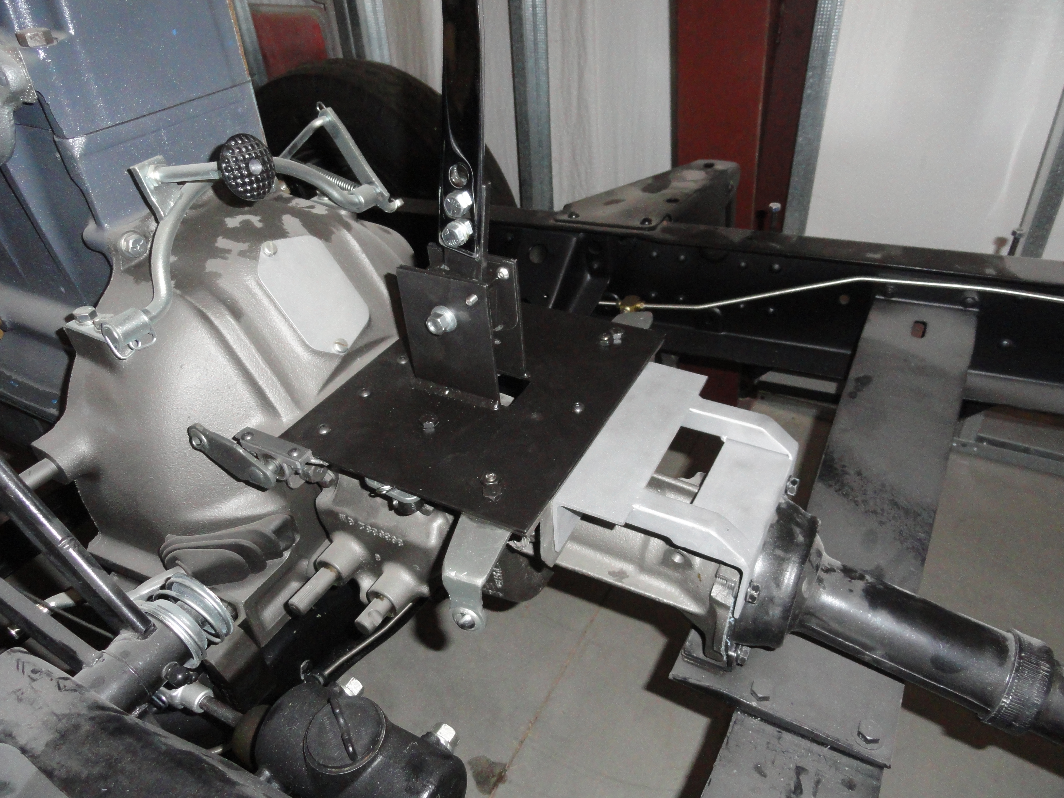
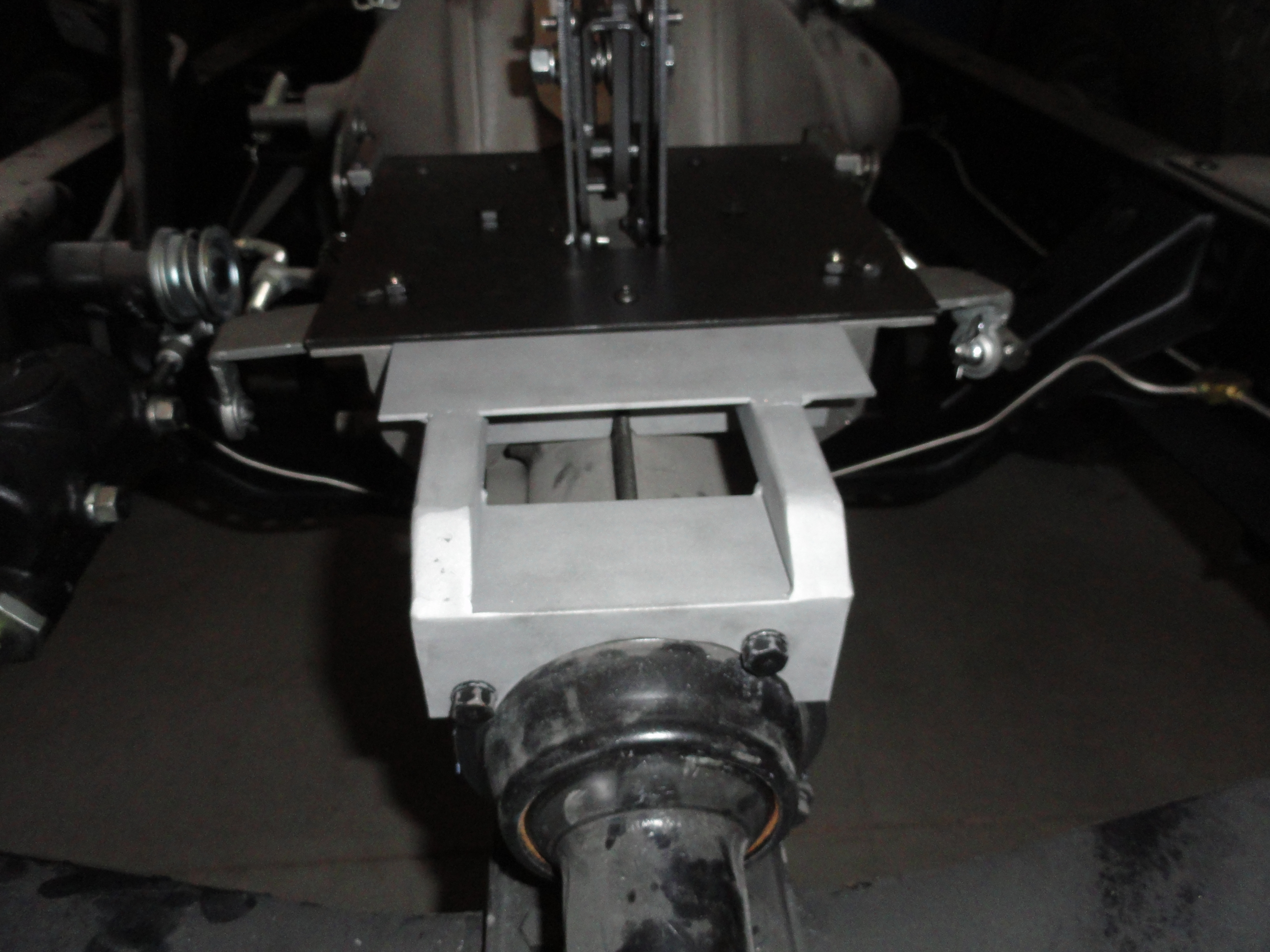 We need to extend the frame so that we can get this thing bolted up nicely. To do that, we will use the top two bolts on the torque tube connection. As with the front bolts, you can re-use the ones that are already there.
Start by cutting two lengths of 1/8" angle iron just like the frame. Cut one that is 7 inches long, and another that is 5-1/4 inches. The long one mates with the rear shifter frame. You will be putting two 5/16" holes in the rear shifter frame once you mark them. You need to mate the two angle iron pieces flush with each other. NOT flush with the top plate! This makes the 2 inch drop just about right for straddling that spline on the 3 speed trans. Our goal here is to make the shifter mechanism level to the ground in all aspects.
If you place a level on your shifter mechanism in both directions, our goal is to make it level. Bolting these two pieces as described will get you close. Now cut two lengths of 3/4" square tubing 4-7/8" inches long. These support runners are just the right size to make a nice clean step-down to the torque tube. The front angle piece looks something like this when you are ready to weld on the runners.Mark the angle iron for placement of the runners. We need to do some surgery on the runners before welding. Here is a side view of the runners.The angle at the right end is more to make it look better than anything. You can either slice the ends with a grinder and fold the top part down to form the angle, or cut it off at a 45 and add metal to fill the hole. The important thing is that the bottom is exactly 4-7/8". This is a critical number because of the placement of the bolt holes on the back of the transmission.
Place the runners so that the left hand runner is inset from the front piece by 5/8". Look at the picture opposite for clarification. The right hand runner will be inset from the front piece by 1 inch. I find it easier to wait until the back piece is made and we can clamp/level everything on the trans before welding.
StockMountBack.jpgThe back piece is made to curve around the torque tube and use the top bolt holes. This is another sculpting job. Start with the bolt holes. They are placed as in the drawing.Follow the full size template. Once you have the sculpting done, and everything looks right, now is a good time to go ahead and bolt the back piece on and check for fitment. Once you have it fit properly, bolt the main shifter frame to the bellhousing bolts tight, clamp the front piece described above on to the main shifter housing. Remember the two angle irons are opposite each other and level with each other, not the top of the shifter housing. Once you have everything test fit, install the runners as needed and make sure everything aligns properly. Clamp as needed or spot weld as needed to keep your alignment. I never said this was going to be easy! Once you have it aligned and ready, weld together permanently.
Now that you have seen every aspect of this project, and you followed my recommendation that you read everything in this guide before starting, you can go back and determine what YOU need for building this permanently. If it's for a stock 3 speed for example, you know you don't have to do ALL of the sculpting on the back of the main frame.
What sticks out to me as being very important that I haven't emphasized yet is the VERY limited space there is below the floor of your cab and the transmission. If you get this wrong in the slightest bit, you won't get your floor cover on. Please observe the importance of this when making the parts for this project. Follow the templates and you will succeed. At the very front of your shifter mechanism, there is less than 7/8" under the shifter frame. In the back it gets better and to the sides it gets better. Use a level to make sure your frame is level with the (flat) ground front to back and side to side.
Assembly
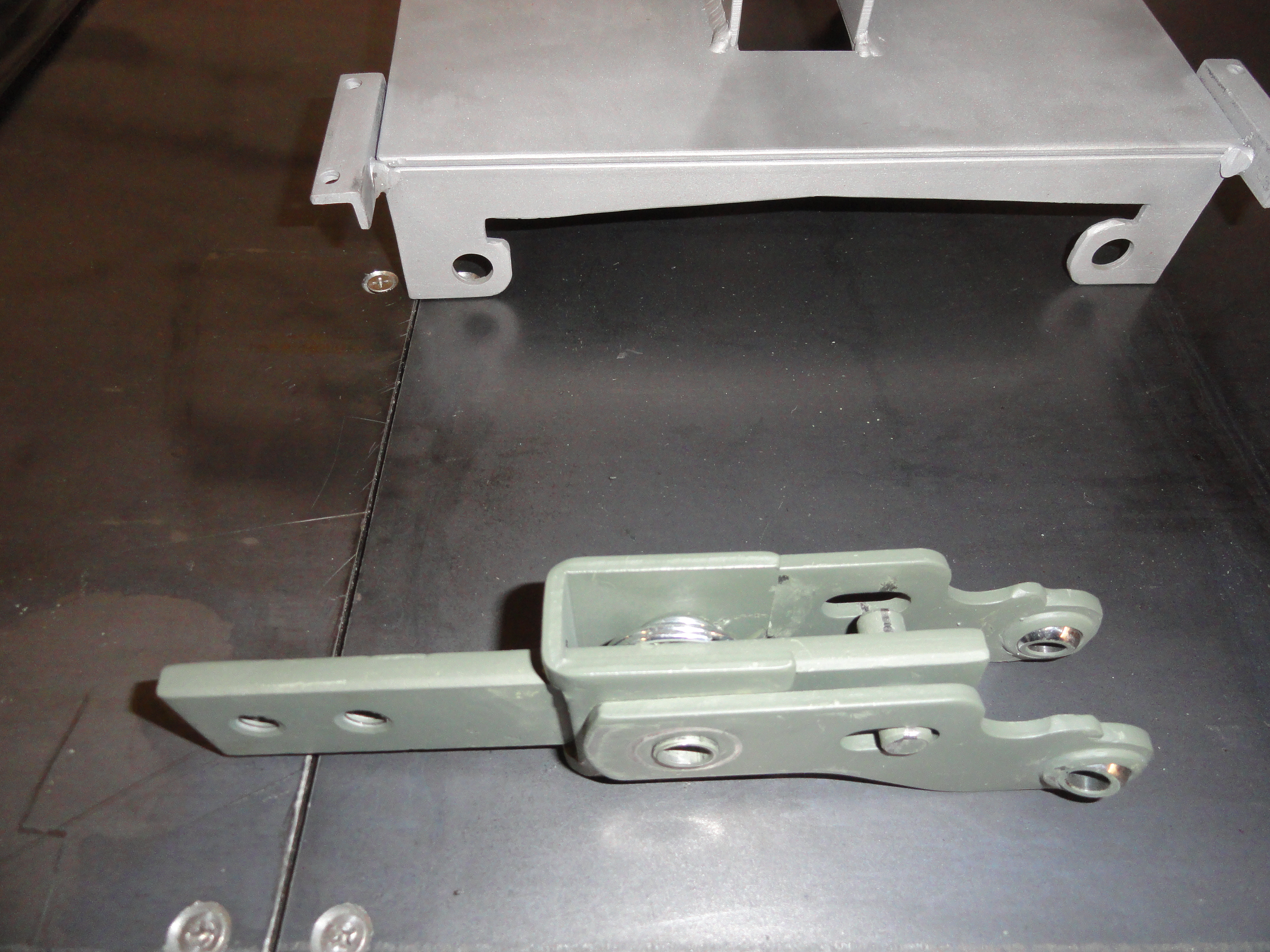
 To assemble the shifter tower mechanism, install so the spring is on the left with the assembly facing front and if using Mr Gaskets mechanism, the arms are pointed as shown.
Slide the assembly into the frame tower carefully observing the above and place the 3/8" through bolt through the tower assembly. Use a split lock washer and snug it down, but do not over-tighten. The two bars with the Heim joints should swing with almost no resistance.
Turn the shifter frame assembly upside down and oriented as shown on page 1.
Installing the Primary Pivots
Install the primary pivots (center ones) by using 5/16"-18 bolts as described in the parts list Number 15. Put the bolt through the Heim joint, then on the back of the pivot, place a special Heim washer on the bolt so that it extends it's ability to rotate as in parts list Number 11. Place the 5/16" round shaft in the pivot through the shifter towers Heim joint first, then place the bolt with the assembled pivot parts through the center hole. Use a lock-washer and low profile nut to tighten. Of course be sure to use the right pivot as per the picture on the left. If you did it right, the pivot should move freely with no resistance and your shifter tower arm should move right along with it. Do this on both sides the same way.NOTE: Because of the super close tolerance of the tower Heim joint and its relation to the pivot, the special Heim washer might be adding too much space and cause binding. Depends on how exact you get the measurements. If the pivot is too high in relation to the tower Heim, remove the special washer and install a relatively thick regular 5/16" washer.
The result should be VERY smooth rotation with no resistance. We want to check this at each step to make troubleshooting easier if you start running into resistance. Don't forget to observe the orientation of the pivots dog leg and shaft placement so you get them on the proper side.
Installing the Secondary Pivots
 With the shifter frame oriented as above, notice that one of your pivots has a higher angle. That is the right side pivot looking at it from this view. You will want that pivot to have its Heim joint down as shown. The first step is securing the threaded rod assembly and buttons. Thread the two buttons (parts list number 7) onto a 4 inch piece of 3/8"-24 all thread. The buttons will be placed on top with the stub protruding downward thru the end hole of each pivot. Secure with one of those hairpin clips. Use a thick enough and stout enough one to never come out. You can also use those circular looking spring clips that came with your Shifter kit (but bend the tab down!). These buttons will never be removed without first removing the entire pivot.
With your buttons and all thread installed properly on the pivot end, place the 3/8" shouldered, 5/16" bolt (parts list number 10) in the center pivot hole and with no washers or anything else, install through the frame. Secure with low profile nut and split lock washer.
Now you have all pivots in place with a piece of all thread with a button on the end of it dangling. The reason we make sure you can attach the two pivots via the rod last is because you will be removing the dangling side of your button a few times during installation. So, place the other button end inside the dogleg, primary pivot. Secure with another hairpin clip but use a thinner and easier to remove one this time. Remember is still has to hold the pivot in when its all over. It may not be easy to install this button in the pivot until you rotate the pivot to a certain place where its looser.
Check your work by holding on to the downward facing (upward right now) Heim joint on the secondary pivot and work the mechanism. Once again, it should be very close to the same smoothness you had before. No resistance and very very easy to rotate.
We are starting with the buttons at 4 inches, but they won't be staying there. During installation you will be adjusting them so that both sides have Neutral exactly across from each other. We can't tell where this is going to be until it's installed.
Installing the Rod/Bearing Assembly
If you followed the previous instruction on this assembly, you may already have installed it. If not mount the rod with the two bearing housings inside the top part of your frame securing them with the #10 screws/nuts. This rod needs to turn with absolutely NO resistance. The E-clips will keep it centered and the pivots are pointing in generally the right place.
 Now you should have something that looks pretty much exactly the same as this picture. The mechanism moves freely and there is no resistance throughout its movement. Don't worry that your mechanism isn't moving through the entire top to bottom area. This is by design. For our old trucks, we don't need that much movement to get the job done. We have one more thing to do before we can start driving around with our new floor shifter. We need to make three linkages. This is what we will do with the rest of that 36" piece of all-thread!
Linkage Creation and Installation
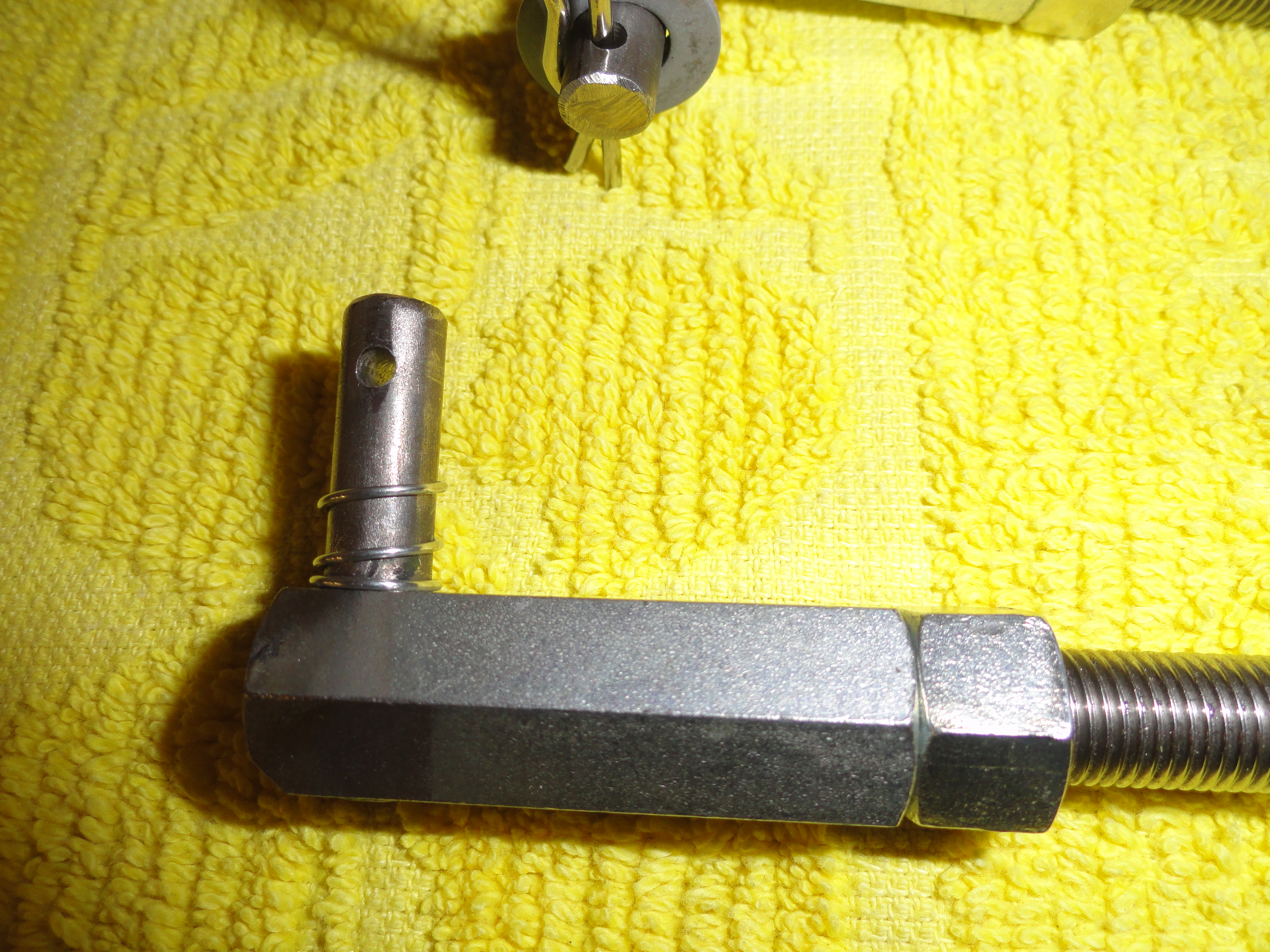
 To make these linkages you will need 6 of the 3/8" long coupling nuts per parts list number 12. On one end about 3/8 of an inch down from the top of the nut, drill a 5/16" hole to accept a piece of 5/16" round stock. The round stock will go completely through the coupling nut and flush with the backside. Cut 6 pieces of 5/16" round stock that is 7/8" long. Drill a 3/16" hole about 1/8" from one end in the center of the rod for placing the cotter pin as shown. The washer and spring is re-used from the trucks current shifter linkage.
Weld the 5/16" rod by placing weld inside that end of the coupling nut. Pretty solid way to hold the rod in. Sometimes things just work out! Now, cut three pieces of 3/8"-24 all thread that is as follows:
- Right Side Bearing Linkage - 6-1/4"
- 1st and Reverse Linkage - 5-1/4"
- 2nd and 3rd linkage - 5"
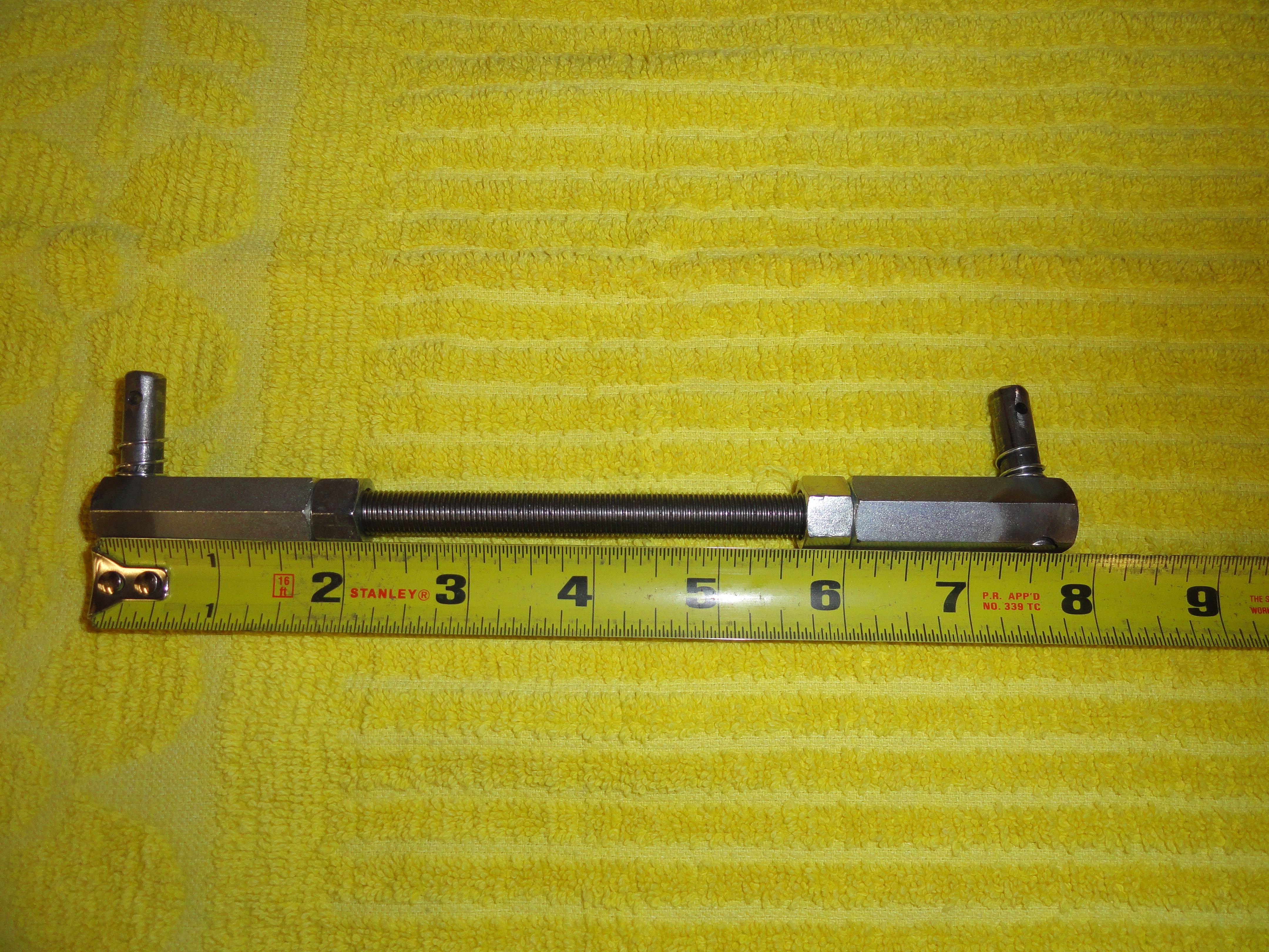 The right side bearing linkage can now be installed. With a 3/8"-24 lock nut spun onto each end of the threaded rod, spin on your linkage ends. Make linkage have an overall length of 7-7/8". Lock them down and install on the outside of your right side bearing pivot assembly. As always, rotate the bearing pivot to ensure everything moves very smoothly. This is the first time you can actually see the movement in action for your Reverse and 1st shift lever on the correct side of the transmission.
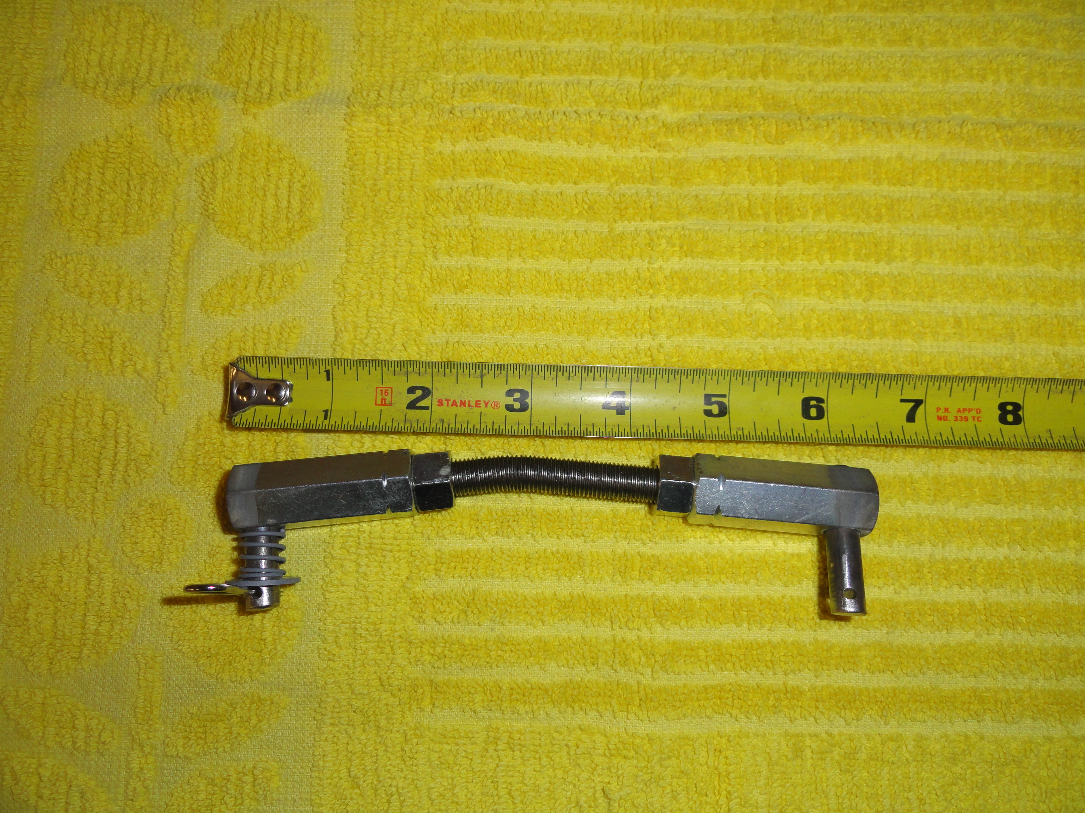 Now we tackle the harder one, the 1st/Reverse linkage. This one is harder because we have to bend it a bit. At 3 inches down one side of the 5-1/4" rod, put a bend in it. How much? I am not an engineer and I really don't know how to tell you, so try this: stand the rod up on end in front of you so the top is at 12 o'clock. Bend the bottom until the bottom is at just a little less than 5 o'clock. No kidding, just a slight bend. 5 o'clock is really a smidge too far. Try not to mess up the threads in doing this. Easier said than done. I use a series of nuts spun together on each side of where I want my bend, then put it in a vise and whack the nuts with the hammer. Put your locking nuts and linkage ends on this piece so its overall length is about 7 inches.
 The 2nd/3rd Linkage is as easy as the first one we did. No bends. Make that one an overall 6-1/4" (using the 5" rod). I added springs to mine that go around the 5/16" rod end to give the linkage more stability and less flopping around. I got the springs from Harbor Freight's Storehouse spring kit. That's also where I got the hairpin clips so I had various sizes. Add a 5/16" washer and you have the same thing they had back in the day.
Finally, once you have your linkages all adjusted and you are happy with all this, you could use some 3/8" heat shrink tubing to dress up the linkages a bit.
Installing and Adjustment
Now that the hard part is over, let's see how we did. Remove the transmission floor cover. If it's the 3 speed one, you will need to purchase the 4 speed cover or modify your old one. You can purchase cloth shifter boots that would work with the 4 speed cover, or go to a lot of trouble and make a tin solution. I am hoping for someone out there to comment with a good idea.
After you have the trans cover removed, remove the top two bolts that hold the transmission to the bell housing. Set the unit on top of the transmission and move it forward and install those two bolts back in, mounting the front of the shifter unit. If it's a stock 3 speed, you can install the additional mount as well. Bolt them together, then remove the top torque tube bolts and use those same bolts to mount the rear. If it's the overdrive model, remove the three intermediate bolts and reinstall them mounting the rear of the unit. That's all there is to mounting.
To test your new shift mechanism but just in case you want to keep your column shifter for now, take the two column shift linkages loose from the transmission levers and tie them back. Install your new linkages. The 2nd/3rd (front trans lever) is really easy. Just put it on to the inside of the two levers. They should be fairly across from each other. The 1st/Rev one will be a little annoying because it's so tight there. Install the linkage with the longer end before the bend at the transmission lever, and the shorter end to the mechanism. The bend points sort of down and directly to the front. It's tight there. If you get totally frustrated and can't get the linkage which goes inside the Heim joint and to the outside of the trans lever, remove the mounting bolts and install the Heim joint side of the linkage, THEN reinstall everything. Whatever works. Once it's there, adjustments happen with it properly installed.So now that everything is mounted, linkages connected, and everything looks right, move the shift levers in your standard H pattern as shown on earlier. Don't expect it to work right, just see where you are. Reverse and One are always engaged until you get to the center, so, are you getting the proper movement to get completely to reverse, through neutral, and completely to first? If no, make the necessary linkage adjustment. Remove the linkage from the trans lever since the other side is so hard. then change the length as needed. Look carefully at the action to make sure nothing is hitting or binding. Once you have the entire movement of the transmission lever at your command at the shift lever, put it in Neutral. Since you did all of the above, it also means your 2nd/3rd lever is in Neutral already. The big question now is, are the two shifter arms inside the tower perfectly across from each other? Chances are they aren't. So, this is where you remove either R/1 or 2/3's primary pivot clip, drop the button and make the threaded rod longer or shorter. Move the pivot by hand once you have dropped the button to see what I am talking about. This adjustment is to get those two bars to be exactly across from each other to form your H pattern. Since you are sitting to the left, you might want to make it so the H pattern is slightly angled toward you to make it feel more natural. Remember, this system should not bind, hang up, or do anything but shift very smoothly. You should feel when each movement "kerthunk's" into place. If your pivot bolts are tight, just the correct amount of slop is there.
So, I ask you, are you happy? Drop me an email at deve@speedprint.com. I want to hear any negative feedback as well. Maybe there is something constructive we can do to make it even better.
Meanwhile, here are those full size templates I promised you. Print these templates out as many times as you need to do it right. What I did when I was using paper templates was to cut the template out with scissors, then tape the template to the work and then using a center punch, hit through the paper in the center of the holes. As long as your printer is printing at 100% they will be in the right place. Be as precise as possible and don't get in a hurry! Follow the instructions here carefully. This was a real confidence builder for me, so I know if I can do it, YOU can do it!
Get the Full Size Templates Here: Full Size Shifter Templates
NOTE: If your computer's printer is like just about everyone else's, it prints at 97% by default. This is bad for our purposes, so whatever you do, go into your printers settings and make sure you find the field where it says 97% and change it to 100%.
The Shifter Handle:
As I stated previously, I had my local machine shop handle this because a metal Lathe is required and I don't have one. To help you get it right the first time, here are the dimensions:
For the Hurst mechanism: 5/8" x26-1/4" High Strength Aluminium keeps the weight down in a place where weight is the enemy. The first 3 inches are squashed so that we can put two 3/8" coarse thread bolts spaced 7/8" apart for mounting the handle. At 8 inches, we make a bend to 36 degrees.
For the Mr Gasket mechanism: 5/8" x26-1/4" High Strength Aluminium keeps the weight down in a place where weight is the enemy. The first 3 inches are squashed so that we can put two 3/8" coarse thread bolts spaced 7/8" apart for mounting the handle. At 8 inches, we make a bend to 53 degrees.
To finish off the top is female threaded to 1-1/2" to accommodate a piece of 3/8-24 All Thread. Cut this about 2-1/4" long and use Loc-Tite, then you can spin your shifter knob on without problems. I got a great looking black with inlaid white pattern knob from a company called Twisted Shiftrz. My favorite knob for this truck is the one available on Stovebolt.com.
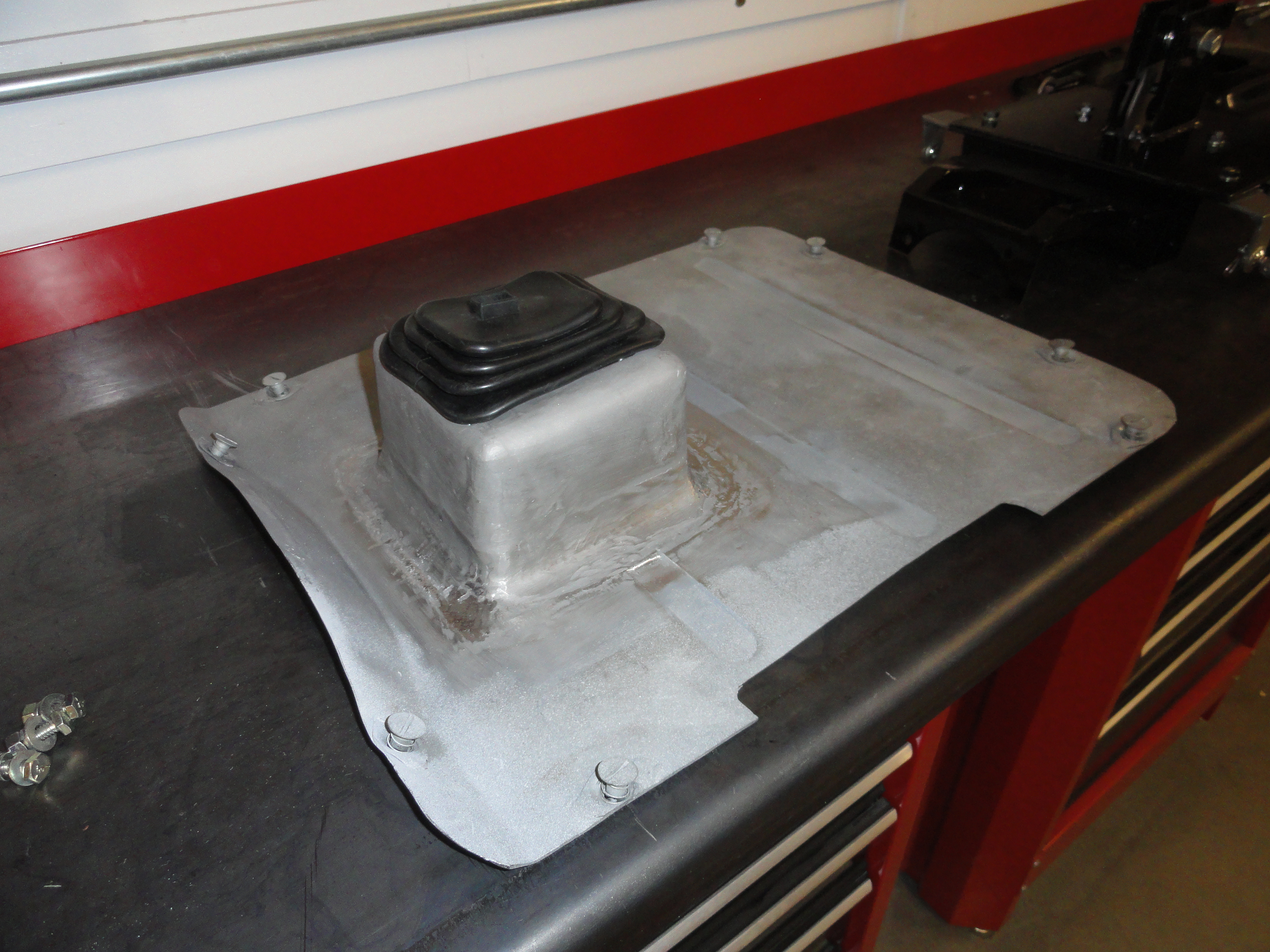
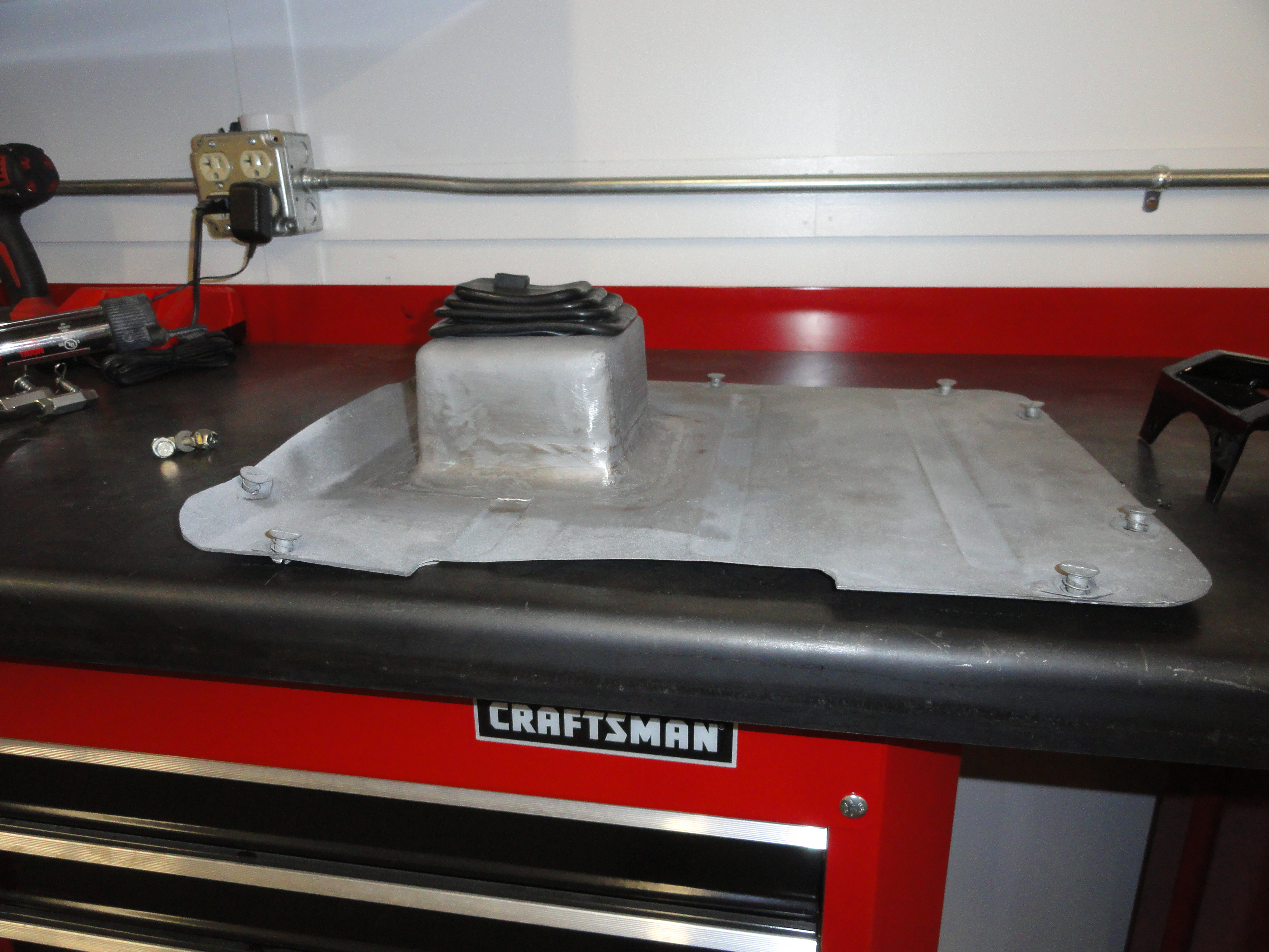 It would really be nice to get some feedback on this one. I know it works perfectly, but the ONE thing I would have liked to figure out better is the boot that covers the tower part of the mechanism. You can purchase them on Ebay Motors for generic use. This is what I came up with for myself. But it's way to involving to do for anyone else with my metalworking toolset. To explain further, as an Avionics Technician in the US Air Force back in the day, I really liked the Dzus Fastener and decided to make my transmission cover accordingly. So there are 1/4 turn fasteners where the sheet metal screws used to go. Then, I put a dual master cylinder in so made a rectangular opening in the floor to accommodate. Lots happening in a short space with this cover, so that's why it looks so different in the pictures.
By the way, if you decide to take a crack at making this shifter mechanism yourself, there are LOTS more pictures available to help you along. If you need someone to make one for you, let me know and I will find someone!
More Pictures available at The Site Archive Page!
This article was first published at DevesTechNet.com (c)2015 All Rights Reserved
Comment