Announcement

Collapse
No announcement yet.

How to use Hand Tools to form those pesky window/windshield corners from Sheet Metal.

Collapse
X
Collapse
  •  

  • How to use Hand Tools to form those pesky window/windshield corners from Sheet Metal.

    This is presented by Robert (MP&C). Robert is an expert in sheet metal fabrication and we are honored to have him write for us! Thanks Robert!

    This Article shows how to inexpensively effect a repair in one of those trouble spots, like windshield corners...

    I just so happen to have a 52 sitting here for a sample, although my w/s is still intact (in the way), so I'm guessing at about a radius of 2.5"

    Click image for larger version  Name:	Picture038-2.jpg Views:	0 Size:	201.3 KB ID:	3681


    I'll use some 5-1/2" square pieces to make the inner and outer corners. This is 18 ga CRS. For the sake of demonstration, I'll use a compass, but for an actual repair the radius would be patterned off the vehicle. Here I used a center punch to keep the compass point from slipping.Click image for larger version  Name:	Picture039-2.jpg Views:	0 Size:	175.1 KB ID:	3682


    Click image for larger version  Name:	Picture041-2.jpg Views:	0 Size:	120.4 KB ID:	3683


    Now mark this out with a sharpie, we'll want to be able to see the mark for awhile


    Click image for larger version  Name:	Picture042-2.jpg Views:	0 Size:	252.7 KB ID:	3685


    Now take the measurement of the depth of the windshield mounting flange. If it sets back from the outer edge say, 3/4", I'd make the flanges on each of these corner repairs 1/2" to allow some trimming.


    Click image for larger version  Name:	Picture043-1.jpg Views:	0 Size:	286.6 KB ID:	3686


    Now repeat for the other piece.


    Click image for larger version  Name:	Picture044-1.jpg Views:	0 Size:	233.8 KB ID:	3687


    When trimming the excess of an inside corner with tin snips, you'll find multiple cuts will help you to get rid of the bulk so the final cut is pretty accurate.


    Click image for larger version  Name:	Picture045-2.jpg Views:	0 Size:	1.33 MB ID:	3688


    Click image for larger version  Name:	Picture046-2.jpg Views:	0 Size:	272.8 KB ID:	3689


    Click image for larger version  Name:	Picture047-2.jpg Views:	0 Size:	248.5 KB ID:	3690


    Here's my 2" dia anvil. As technical as this stuff is you can use whatever is handy and works.
    Click image for larger version  Name:	Picture048.jpg Views:	0 Size:	271.6 KB ID:	3691


    I keep the line at the top where I can see what's going on. The first tap with the hammer will show if you are off from your bend line, as you can see. This will show where you are so you can readjust your placement with the next tap, if needed.

    Click image for larger version  Name:	Picture049-1.jpg Views:	0 Size:	108.8 KB ID:	3692

    Looking at the picture, you can see that the length of our bend line is shorter than the outer perimeter of the flange it is going to form. In essence, once you try to make a 90 degree bend, this excess metal will have a tendency to push the outer corners up.


    Click image for larger version  Name:	Picture050-1.jpg Views:	0 Size:	264.4 KB ID:	3693


    Click image for larger version  Name:	Picture051-1.jpg Views:	0 Size:	258.8 KB ID:	3694


    Click image for larger version  Name:	Picture052.jpg Views:	0 Size:	229.9 KB ID:	3695

    ....so we'll need some shrinking here to bring things flat again. We'll need what's called a "tucking tool", and I have made one here out of a large pair of needle nose I never used for anything else. Please note that all sharp edges of the pliers have been rounded off to prevent cutting the metal.


    Click image for larger version  Name:	Picture053-1.jpg Views:	0 Size:	226.9 KB ID:	3696


    Click image for larger version  Name:	Picture054.jpg Views:	0 Size:	263.9 KB ID:	3697


    After using the tool to make some "tucks", the object is to heat up the high spot of the tucks, place the two lower edges of the tucks so they are resting against your rounded "anvil", and using a flat hammer, tap the high spot back into itself (flatten it out) repeat as necessary until the panel flange is bent to the degree you want, and the panel is flat across.


    Click image for larger version  Name:	Picture057.jpg Views:	0 Size:	255.0 KB ID:	3698


    If you're working by yourself, be sure to have a good, secure means to hold your heating device, like a BFG tire.


    Click image for larger version  Name:	Picture058.jpg Views:	0 Size:	253.6 KB ID:	3699


    Click image for larger version  Name:	Picture060.jpg Views:	0 Size:	220.2 KB ID:	3700


    Much better than before, now for the outer piece. This has a slight radius, so I'll do some more grinding on the welding table to provide one:


    Click image for larger version  Name:	Picture061.jpg Views:	0 Size:	181.1 KB ID:	3701


    Click image for larger version  Name:	Picture062.jpg Views:	0 Size:	182.5 KB ID:	3702


    Click image for larger version  Name:	Picture064.jpg Views:	0 Size:	234.8 KB ID:	3703


    As before, the bend line is of different length than the outer flange perimeter. Here the outer dimension is shorter, so it will have a tendency to pull the panel downward as the bend occurs. To get rid of this issue, we will need to stretch the metal, and a slightly crowned hammer will help out.


    Place the flange on a flat surface and using the hammer, work the area, especially the outer perimeter where it is shorter, this needs more stretching.


    Click image for larger version  Name:	Picture065.jpg Views:	0 Size:	246.4 KB ID:	3704


    Click image for larger version  Name:	Picture067.jpg Views:	0 Size:	243.4 KB ID:	3705


    It doesn't take long to notice an improvement. Keep working as needed until you have the correct bend you're looking for.


    Click image for larger version  Name:	Picture068.jpg Views:	0 Size:	204.8 KB ID:	3706

    Here I'll normally trim one flange to a nice straight cut, position the other so you have your correct offset, and scribe and trim the other. Weld together, Dress (grind) the welds, and install.


    Click image for larger version  Name:	Picture070.jpg Views:	0 Size:	316.4 KB ID:	3707


    Click image for larger version  Name:	Picture071.jpg Views:	0 Size:	191.8 KB ID:	3708


    Click image for larger version  Name:	Picture072.jpg Views:	0 Size:	296.5 KB ID:	3709


    And there you have it, windshield corner repairs on a budget...... Now granted, this covers just doing the basic shape, but once you reach this point adding any bead details will just be a bit more hammer work..
    Attached Files

    Last edited by Deve; 09-15-2020, 10:46 PM.
      Posting comments is disabled.

    Categories

    Collapse

    Article Tags

    Collapse

    There are no tags yet.

    Latest Articles

    Collapse

    • How to use Hand Tools to form those pesky window/windshield corners from Sheet Metal.
      by Deve
      This is presented by Robert (MP&C). Robert is an expert in sheet metal fabrication and we are honored to have him write for us! Thanks Robert!

      This Article shows how to inexpensively effect a repair in one of those trouble spots, like windshield...
      11-18-2015, 09:36 AM
    • Sail to the USA in your 1950's Chevy Truck!
      by Deve
      Note: As with all of the content on this website, you can simply click on any picture to get its largest size. In this way, we can maintain the clearest definition to make it easier for you to see the detail. If the picture is so big you can't see all of it on your screen, all you have to do is hold down CONTROL and move the mouse wheel up and down to resize!

      I was minding my own business one day in 2005 when I got a phone call from this English Bloke named Peter Spencer. Peter tells me he is from a movie producing company named PixWorks. I forget how he said he got my name, but he wanted to do a movie based on the real life Saga of Luis Grass and his attempt to float a 1951 Chevy 1-1/2 ton Truck from Cuba to the USA. Logo by my son Kelly at Krehbiel.co.

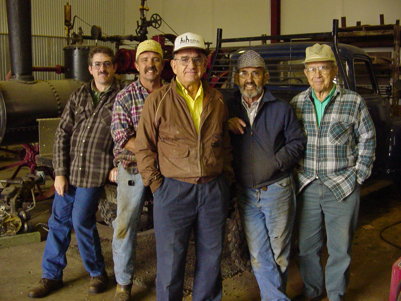
      He went on to say that he was hoping for engineering expertise in duplicating this truck for the movie. I took his word for it because he sounded convincing enough and although we hadn't seen any money yet, I asked a few friends of mine if they would be interested in helping with this project. My team was made up of all engineers who got a kick out of the story and felt compelled to help. Right is the Engineering Team that never was. Left to Right: Deve Krehbiel, Stan Swartzendruber, Richard Swartzendruber, Gene Swartzendruber and Wayne Swartzendruber. In case you are wondering why we are so Swartzendruber heavy in this endeavor it's because those brothers (and son) are renowned in this area for their engineering expertise. You have to honor someone who defied the odds and went to these extremes for his family. So we were pretty excited about it. ...
      02-14-2015, 12:10 PM
    • Lazze's Work Holding Jig
      by Deve


      This is the video I was talking about in the Shop Section of The Think Tank....
      01-02-2015, 04:06 PM
    Working...
    X